3D Modeling
By creating 3D models with triangles or quads on a surface, the model is formed using a polygon mesh [1]. This mesh consists of all the vertices shown in the first image as Fig. 1.
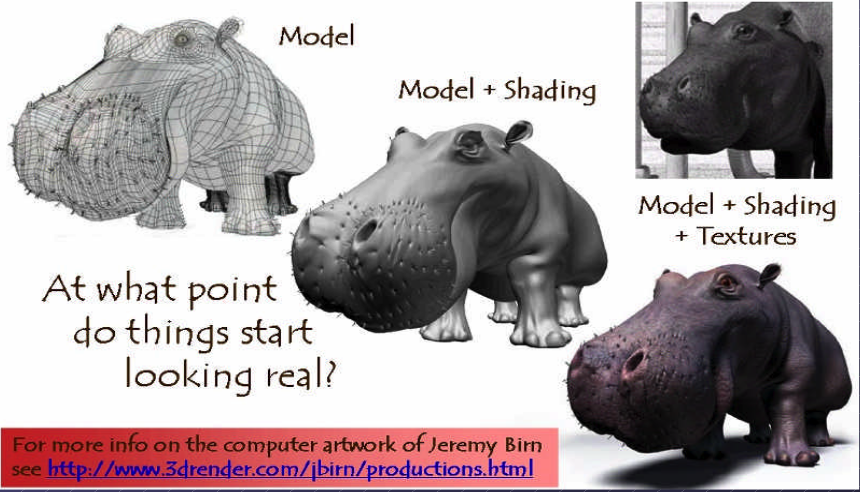
Fig. 1 Creating 3D model and texturing
After applying smooth shading [1], the vertices and edge lines are covered with color (or the edges are visually removed — edges never actually have black outlines). As a result, the model appears much smoother [2].
Furthermore, after texturing (texture mapping), the model looks even more realistic [3].
Animation
★ Animation Layers: High → Low
This breakdown organizes animation systems from the highest gameplay logic down to the lowest GPU skinning, and clearly marks which parts are controlled by the user and which parts are handled by the 3D engine.
Gameplay Animation Logic (High Level): set by user (game developer)
See video here [4].
Examples
Play “walk” when speed > 0.1
Trigger “jump” on button press
Switch to “attack” when enemy detected
Blend run when velocity increases
Where it lives
Live in gameplay scripts (C#, Blueprints, GDScript, Python)
Unity: C# scripts
Unreal: Blueprints or C++
Godot: GDScript
ThinMatrix: Java (no scripting layer)
This layer decides when animations should play.
Animation State Machine / Animation Graph: set by user (game developer)
Examples
Idle → Walk → Run transitions
Blend trees
Animation layers (upper body, lower body)
Animation parameters (speed, grounded, direction)
Where it lives
Unity: Animator Controller
Unreal: Animation Blueprint
Godot: AnimationTree
ThinMatrix: Does not have this layer
This layer controls which animation clip is active and how transitions occur.
Animation Clip Playback Layer: user chooses
An animation clip is a sequence of keyframes over a period of time that represents a motion or action.
Examples
Play animation clip
Loop animation
Set animation speed
Crossfade between clips
Blend two clips together
Who sets it? User chooses which clip to play.
Who implements it? Engine handles blending, timing, and playback.
Where it lives
Unity: Mecanim runtime
Unreal: AnimInstance
Godot: AnimationPlayer
ThinMatrix: Java engine code (Animator.java)
This layer executes the user’s choices.
Skeleton Animation System (Low Level): 3D engine implements it
Examples
Bone hierarchy
Keyframe interpolation
Joint transforms
Matrix palette generation
Pose calculation
Who sets it? Engine
Who uses it? User indirectly, by playing animations.
Where it lives
Unity: C++ engine core
Unreal: C++ engine core
Godot: C++ engine core
ThinMatrix: Java engine code (he writes this manually)
This layer performs the mathematical work of animation.
GPU Skinning (Lowest Level): 3D engine implements it
Examples
Vertex shader skinning
Applying bone matrices
Weighted vertex deformation
Sending matrices to GPU
Who sets it? Engine
Who uses it? User never touches this layer directly (except in custom engines).
Where it lives
Unity: C++ + HLSL
Unreal: C++ + HLSL
Godot: C++ + GLSL
ThinMatrix: GLSL shader he writes manually
This is the final stage where the GPU deforms the mesh.
Full Hierarchy (Summary)
HIGH LEVEL (User)
──────────────────────────────────────────────
1. Gameplay Animation Logic
2. Animation State Machine / Animation Graph
3. Animation Clip Playback

LOW LEVEL (Engine)
──────────────────────────────────────────────
4. Skeleton Animation System
5. GPU Skinning
Developers only write the highest‑level animation logic and designed transitions & blends as shown in Fig. 2. The engine automatically handles all lower‑level animation work. Like the video [4], Jason’s tutorials operate only in Level 1 and Level 2:
✔ Level 1 — Scripts
He writes code like:
animator.SetFloat("Speed", speed);
✔ Level 2 — State Machine
He configures transitions and parameters.
![digraph AnimationLayers {
rankdir=TB;
node [shape=box, style=rounded, fontsize=12];
High1 [label="1. Gameplay Animation Logic\n(User scripts / gameplay code)"];
High2 [label="2. Animation State Machine / Animation Graph\n(User-designed transitions & blends)"];
Mid [label="3. Animation Clip Playback\n(Engine-controlled timing & blending)"];
Low1 [label="4. Skeleton Animation System\n(Bone transforms, keyframe interpolation)"];
Low2 [label="5. GPU Skinning\n(Vertex shader applies bone matrices)"];
High1 -> High2 [label="animation intent\n(e.g., walk, run, jump)"];
High2 -> Mid [label="selected clip + blend parameters"];
Mid -> Low1 [label="sampled pose\n(bone transforms per frame)"];
Low1 -> Low2 [label="matrix palette\n(bone matrices sent to GPU)"];
}](_images/graphviz-a225b560ceff9938339eb3adeb9d630c05991999.png)
Fig. 2 Animation levels
ThinMatrix’s engine collapses the top three layers into Java because it has no scripting layer and no animation graph, so the user must modify the engine code directly.
According to the video on ThinMatrix’s skeleton animation [5], he is sampling the animation clip at different times. The animation clip already contains: keyframes, bone transforms, timestamps, interpolation curves. All of this comes from Blender’s exported .dae file. Joints are positioned at different poses at specific times (keyframes), as illustrated in Fig. 3.
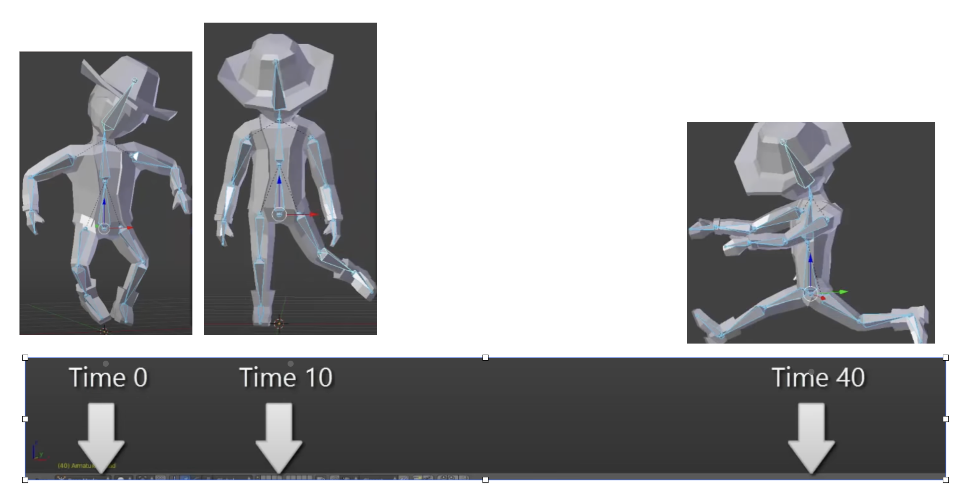
Fig. 3 Get time points at keyframes
Although most of 3D game engines are written C++, ThinMatrix’s engine is 100% Java. In this series of videos, you will see that he writes new Java engine modules, edits existing engine code, loads animation data from Blender, interpolates keyframes, updates bone matrices and sends them to the GPU. Because ThinMatrix’s engine is tiny and educational for engine programmer or game developer, does not provide Scripting Layer (such as C#, Python, GDScript, Blueprints) most commercial 3D engines. Instead, he modifies ThinMatrix’s Java engine directly, which differs from most other 3D engines operate.
Animation flow
Every modern 3D animation tool comes with its own built‑in render engine, and often more than one. In 3D game design, game engines (Unity, Unreal, Godot) use real‑time engines for real-time animation.
Pipeline: Blender → Engine → OpenGL
+------------------+
|     Blender      |
|  (Modeling Tool) |
+------------------+
          |
          |  Exports assets:
          |  - Meshes (.obj, .fbx, .gltf)
          |  - Armatures / bones
          |  - Animations (keyframes)
          |  - Textures (PNG, EXR, TGA)
          v
+---------------------------+
|       Game Engine         |
| (Unity, Unreal, Godot,    |
|  LWJGL, JOGL, Custom)     |
+---------------------------+
          |
          |  Engine loads assets:
          |  - Parses mesh data
          |  - Loads skeletons
          |  - Loads animation curves
          |  - Loads materials/shaders
          |
          |  Engine code you write:
          |  - Java (JOGL/LWJGL)
          |  - C++ (custom engine)
          |  - C# (Unity)
          |  - GDScript/C++ (Godot)
          |
          |  Engine compiles shaders:
          |  - GLSL (OpenGL)
          |  - HLSL (DirectX)
          |  - SPIR-V (Vulkan)
          v
+---------------------------+
|         Renderer          |
|    (OpenGL / Vulkan /     |
|     DirectX / Metal)      |
+---------------------------+
          |
          |  GPU receives:
          |  - Vertex buffers
          |  - Index buffers
          |  - Textures
          |  - Uniforms (matrices, bones)
          |  - Compiled shaders
          v
+---------------------------+
|            GPU            |
| (Vertex Shader → Raster → |
|  Fragment Shader → Frame) |
+---------------------------+
          |
          v
+---------------------------+
|        Final Image        |
|     (On your screen)      |
+---------------------------+
Note
- 3D modeling tools do store animation and movement data
— but they do NOT store any rendering or API‑specific code.
- Game engines do store animation data
— but programmers still write the logic that plays, blends, and controls those animations.
Animation Data vs. Movement Speed in Games
List the animation types in a table for inclusion in this book.
Animation Type |
What Moves |
Description |
GPU Requirement |
|---|---|---|---|
Transform Animation |
Object transform |
The entire mesh moves as a rigid body using position, rotation, and scale. No vertex-level deformation occurs. |
Optional (fixed-function or shaders) |
Skinning |
Vertex positions |
Vertices are blended by bone matrices to deform the mesh (arms bending, legs walking). Requires per-vertex matrix blending. |
Requires shaders |
Morph Target Animation |
Vertex positions |
Vertices blend between multiple stored shapes (facial expressions, muscle bulges). Uses morph weights to interpolate. |
Requires shaders |
Procedural Deformation |
Vertex positions |
Vertices are modified by mathematical functions (wind, waves, noise, squash-and-stretch). Driven by time or simulation parameters. |
Requires shaders |
Example: Walking Animation: Skinning + Transform Animation
When a character walks in a game, the animation is produced by two different systems working together:
Skinning (Bone Animation) Skinning is responsible for deforming the mesh. It drives the motion of limbs such as legs, arms, spine, and feet. Without skinning, the character would move as a rigid statue with no bending or articulation.
Transform Animation (Rigid-Body Movement) Transform animation moves the entire character through the world. This includes translation, rotation, and root motion. Without transform animation, the character would walk in place without actually moving forward.
Root bone: the bone that represents the entire object’s transform — the top‑most parent of the hierarchy. An example of person:
Root
 └─ Pelvis
     ├─ Spine
     │   ├─ Chest
     │   │   ├─ Neck
     │   │   │   └─ Head
     │   │   └─ Shoulders
     │   │       ├─ Arm_L
     │   │       └─ Arm_R
     ├─ Leg_L
     └─ Leg_R
Both systems are required to create a complete walking animation:
Skinning provides the internal limb motion.
Transform animation provides the external world-space movement.
Together, they produce the final effect of a character walking naturally through the environment.
The following explains what animation data 3D modeling tools store, what game engines store, and what programmers must implement manually. It also clarifies the relationship between animation curves, movement speed, and gameplay logic.
What 3D Modeling Tools Actually Store
3D modeling and animation tools such as Blender, Maya, and 3ds Max store animation data, not gameplay logic.
They do store:
Keyframes (frame 0, frame 10, frame 24, etc.)
Bone transforms at each keyframe
Interpolation curves (Bezier, linear, quaternion)
Animation duration (e.g., 1.2 seconds)
Frame rate (e.g., 24 fps)
Skeleton hierarchy
Skin weights (vertex-to-bone influences)
Optional root bone motion (displacement over time)
Modeling tools produce data, not rendering code and not gameplay rules in OpenGL/DirectX code.
Example:
Bone "Arm" rotation at frame 0 = (0°, 0°, 0°)
Bone "Arm" rotation at frame 10 = (45°, 0°, 0°)
What Game Engines Actually Store
The engine’s built‑in C++ renderer handles all OpenGL/Vulkan/Metal calls automatically. Game engines such as Unity, Unreal Engine, Godot, or custom engines store and manage animation data, but still do not define gameplay movement speed.
They do store:
Animation clips
State machines (Idle → Walk → Run)
Blend trees
Transition rules
Animation events
Curves for rotation, scaling, and root motion
Again: data, not OpenGL/DirectX code.
Example:
If speed < 0.1 → Idle
If speed > 0.1 → Walk
If speed > 4.0 → Run
This is engine logic, not GPU code.
Game engines interpret animation data but rely on programmer logic to control how characters move in the world.
What Programmers Must Implement
Programmers write the logic that uses animation data to move objects.
Examples:
In Unity (C#)
animator.SetFloat("speed", playerVelocity);
...
float speed = 3.5f;
transform.position += direction * speed * Time.deltaTime;
In a custom engine (C++/OpenGL)
shader.setMatrix("boneMatrices[0]", boneMatrix);
...
float velocity = 3.5f;
position += velocity * deltaTime;
In JOGL/LWJGL (Java)
glUniformMatrix4fv(boneLocation, false, boneMatrixBuffer);
...
float velocity = 3.5f;
position += velocity * deltaTime;
Programmers write:
Programmers implement:
Movement speed
E.g. Set the value for speed or velocity as the code above.
Acceleration and deceleration
Physics integration
AI movement
Player input
Animation blending logic
Uploading bone matrices to the GPU
GLSL shader code for skinning
Animation data is used by code, not replaced by it.
Root Motion vs. Movement Speed
Some animations include root motion, where the root bone moves forward during a walk cycle. Modeling tools export this as bone displacement over time, but they still do not define speed.
Example:
If the root bone moves 1 meter in 0.5 seconds, the engine can compute:
speed = 1m / 0.5s = 2 m/s
However:
Blender does not store “2 m/s”
The engine derives speed from displacement
Programmers decide whether to use root motion or in-place animation
Summary Table
Concept |
Stored in Blender? |
Stored in Engine? |
Controlled by Programmer? |
|---|---|---|---|
Keyframes |
Yes |
Yes |
No |
Bone transforms |
Yes |
Yes |
No |
Animation length |
Yes |
Yes |
No |
Movement speed |
No |
Yes (derived) |
Yes |
Physics movement |
No |
Yes |
Yes |
AI movement |
No |
Yes |
Yes |
Final Clarification
3D modeling tools store animation timing, not gameplay speed.
Game engines store animation clips, not movement speed.
Programmers control movement speed, physics, and gameplay behavior.
No tool generates JOGL/OpenGL/Vulkan/DirectX code.
All rendering API calls are written by engine developers or by you in a custom engine.
Example for accelerating playing
Animation Speed vs Engine Rendering (5× Speed)
The following table shows how animation playback, movement speed, and GPU rendering interact when the gameplay speed is multiplied by five. The animation remains 24 fps internally, but its playback time advances five times faster. The GPU continues to render at 60 fps and samples the animation at the current time.
Property |
Original Value |
After 5× Speed |
|---|---|---|
Animation FPS (baked) |
24 fps |
24 fps (unchanged) |
Animation Playback Speed |
1× |
5× |
Steps per Second |
6 steps/sec |
30 steps/sec |
Movement Speed |
6 m/sec |
30 m/sec |
GPU Rendering FPS |
60 fps |
60 fps |
Engine Playing Frames (What GPU Displays) |
Samples animation at 60 fps |
Samples animation at 60 fps (skips/interpolates intermediate animation frames) |
Summary:
The animation does not become 120 fps; it is simply played 5× faster.
The runner appears to take 30 steps per second and move 30 meters per second.
The GPU still renders 60 frames per second.
The engine samples the animation at each rendered frame, so it effectively displays every fifth animation sample, using interpolation for smoothness. For this case, it may display 1 out of 2 animation frames from 3D modeling.
Node-Editor (shaders generator)
3D animation tools (Blender, Maya, Houdini) use render engines and node editors for materials, lighting, and effects.
Game engines (Unity, Unreal, Godot) use real‑time engines and node editors for shaders, VFX, and sometimes logic.
A node editor defines the entire material that is applied to the surface of a 3D object. The shader generated from the node graph runs on every pixel (fragment) of the object’s surface. In this sense, the node editor controls the whole surface, not only a specific region.
However, the node graph can include masks, textures, vertex colors, or procedural patterns that allow the artist to specify which parts of the surface receive a particular effect. These masks do not limit the shader to only part of the surface; instead, they instruct the shader how to behave differently across different regions.
Node-Editor
Example
Let’s say you want:
rust only on the edges
metal everywhere else
In the node editor:
Load a rust texture
Load a metal texture
Use a mask (curvature or hand-painted)
Mix them using a Mix node
The shader still runs on the whole surface, but the mask tells it:
“Use rust here”
“Use metal here”
In summary:
The node editor defines the full material for the entire surface.
Artists can use masks or textures to target specific areas within that surface.
The shader still executes globally, but its output varies based on the mask inputs.
Thus, a node editor controls the whole surface, while masks determine how different parts of that surface are shaded.
For 3D video game engines, the only case where mask data is inside the model file is vertex colors. Everything else lives in textures or material/shader assets.
Procedural Rust on Edges Using Shader Nodes
To demonstrate how to create a rust-on-edges material using Blender’s shader node editor as shown in Fig. 4. The goal is to reproduce the effect commonly used on metal containers: clean metal on flat surfaces and rust accumulation along exposed edges.
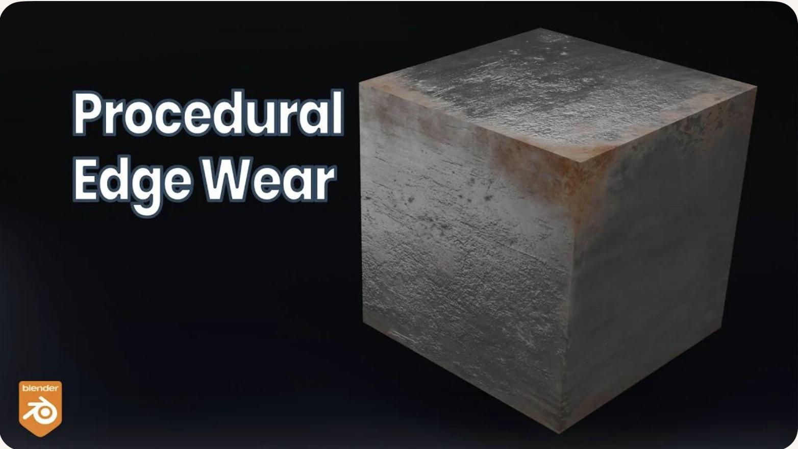
The technique relies on three core ideas:
Detecting edges using the Bevel or Pointiness attribute.
Creating a mask that isolates only the worn edges.
Blending a rust material with a metal material using that mask.
This workflow is fully procedural and does not require painting or external textures.
Procedural Edge Wear Node Graph (ASCII Diagram) to create Fig. 4 in video [6] includes 1. edge detection, 2. mask breakup, 3. material creation, and 4. final blending as follows:
+================================================================+
|                    1.  EDGE DETECTION BLOCK                    |
|                     (Generating an Edge-Wear Mask)             |
+================================================================+

   Geometry Node
        |
        |----> Pointiness (Cycles only)
        |
   Bevel Node (Eevee/Cycles)
        Radius = 0.01–0.03
        |
        v
   ColorRamp (Sharpen edge highlight)
        |
        v
   Edge Mask (base convex-edge detection)


+================================================================+
|              2. MASK BREAKUP / RANDOMIZATION BLOCK             |
|               (Refining the Mask With Noise Textures)          |
+================================================================+

   Noise Texture (Scale 5–15)
        |
        v
   ColorRamp (optional shaping)
        |
        v
   Multiply Node  <---------------- Edge Mask
        |
        v
   ColorRamp (final threshold control)
        |
        v
   Final Edge Wear Mask

material creation
+================================================================+
|                      3. MATERIAL BLOCK                         |
|                       (Base Material Structure)                |
+================================================================+

   METAL MATERIAL:
        Principled BSDF
        Metallic = 1.0
        Roughness = 0.2–0.4

   RUST MATERIAL:
        Principled BSDF
        Base Color = orange/brown
        Roughness = 0.7–1.0
        Optional Noise → color variation
        Optional Bump → rust height


+================================================================+
|                      4. BLENDING BLOCK                         |
|                       (Blending Metal and Rust Materials)      |
+================================================================+

   Metal BSDF ----------------------+
                                    |
                                    v
                               Mix Shader ----> Material Output
                                    ^
                                    |
   Rust BSDF -----------------------+
                                    |
                                    |
                         Final Edge Wear Mask (Fac)
Code Generation from Node-Editor
Node-based shader editors are visual tools used in modern game engines and DCC (Digital Content Creation) software. They allow users to build shaders by connecting nodes instead of writing GLSL, HLSL, or Metal code manually. These editors do generate shader code automatically.
Node-Based Editors Do Generate Shader Code
Node-based shader editors such as:
Unity Shader Graph
Unreal Engine Material Editor
Godot Visual Shader Editor
Blender Shader Nodes (for Eevee/Cycles)
all compile the visual node graph into real shader code.
Depending on the engine, the generated code may be:
GLSL (OpenGL / Vulkan)
HLSL (DirectX)
MSL (Metal)
SPIR-V (Vulkan intermediate format)
The generated code is usually not shown to the user, but it is compiled and sent to the GPU at runtime.
How Users Generate Shader Code with Nodes
The workflow for generating shader code through a node editor typically looks like this:
The user opens the shader editor.
The user creates nodes representing:
math operations (add, multiply, dot product)
texture sampling
Determine FS.
lighting functions
color adjustments
UV transformations
The user connects nodes visually to define the shader logic.
Defines surface color,lighting, and texture sampling → determine FS.
For simple deformations (waves, wind, dissolve) → determine the VS.
Generate both TCS and TES code for displacement and subdivision control.
GS code is typically written manually by graphics programmers since primitives culling and clipping are not related with model resolution and texture materials.
The engine converts the node graph into an internal shader representation.
The engine compiles this representation into platform-specific shader code (GLSL, HLSL, MSL, or SPIR-V).
The compiled shader is sent to the GPU and used for rendering.
The user never writes the shader code directly; the editor generates it automatically.
Who Is the “User” of Node-Based Editors?
The typical users of node-based shader editors are:
- Graphics Designers / Technical Artists
Primary users.
They create visual effects, materials, and surface shaders.
They usually do not write GLSL or HLSL manually.
Node editors allow them to work visually without programming.
- Software Programmers / Graphics Programmers
Secondary users.
They may create custom nodes or extend the shader system.
They write low-level shader code when needed.
They integrate the generated shaders into the rendering pipeline.
In most workflows:
Graphics designers build the shader visually.
The engine generates the shader code.
Programmers handle advanced logic, optimization, or custom nodes.
Summary
Node-based shader editors do generate shader code automatically.
Users generate shaders by connecting visual nodes rather than writing GLSL/HLSL manually.
The primary “user” is the graphics designer or technical artist.
Programmers support the system by writing custom nodes or low-level shaders when needed.
The shaders introduction is illustrated in the next section OpenGL.
3D Modeling Tools
Every CAD software manufacturer, such as AutoDesk and Blender, has their own proprietary format. To solve interoperability problems, neutral or open source formats were created as intermediate formats to convert between proprietary formats.
Naturally, these neutral formats have become very popular. Two famous examples are STL (with a .STL extension) and COLLADA (with a .DAE extension). Below is a list showing 3D file formats along with their types.
3D file format |
Type |
|---|---|
STL |
Neutral |
OBJ |
ASCII variant is neutral, binary variant is proprietary |
FBX |
Proprietary |
COLLADA |
Neutral |
3DS |
Proprietary |
IGES |
Neutral |
STEP |
Neutral |
VRML/X3D |
Neutral |
The four key features a 3D file can store include the model’s geometry, the model’s surface texture, scene details, and animation of the model [7].
Specifically, they can store details about four key features of a 3D model, though it’s worth bearing in mind that you may not always take advantage of all four features in all projects, and not all file formats support all four features!
3D printer applications do not to support animation. CAD and CAM such as designing airplane does not need feature of scene details.
DAE (Collada) appeared in the video animation above. Collada files belong to a neutral format used heavily in the video game and film industries. It’s managed by the non-profit technology consortium, the Khronos Group.
The file extension for the Collada format is .dae. The Collada format stores data using the XML mark-up language.
The original intention behind the Collada format was to become a standard among 3D file formats. Indeed, in 2013, it was adopted by ISO as a publicly available specification, ISO/PAS 17506. As a result, many 3D modeling programs support the Collada format.
That said, the consensus is that the Collada format hasn’t kept up with the times. It was once used heavily as an interchange format for Autodesk Max/Maya in film production, but the industry has now shifted more towards OBJ, FBX, and Alembic [7].