Cpu0 Architecture and LLVM Structure
Before you begin this tutorial, you should know that you can always try to develop your own backend by porting code from existing backends. The majority of the code you will want to investigate can be found in the /lib/Target directory of your root LLVM installation. As most major RISC instruction sets have some similarities, this may be the avenue you might try if you are an experienced programmer and knowledgable of compiler backends.
On the other hand, there is a steep learning curve and you may easily get stuck debugging your new backend. You can easily spend a lot of time tracing which methods are callbacks of some function, or which are calling some overridden method deep in the LLVM codebase - and with a codebase as large as LLVM, all of this can easily become difficult to keep track of. This tutorial will help you work through this process while learning the fundamentals of LLVM backend design. It will show you what is necessary to get your first backend functional and complete, and it should help you understand how to debug your backend when it produces incorrect machine code using output provided by the compiler.
This chapter details the Cpu0 instruction set and the structure of LLVM. The LLVM structure information is adapted from Chris Lattner’s LLVM chapter of the Architecture of Open Source Applications book [10]. You can read the original article from the AOSA website if you prefer.
At the end of this Chapter, you will begin to create a new LLVM backend by writing register and instruction definitions in the Target Description files which will be used in next chapter.
Finally, there are compiler knowledge like DAG (Directed-Acyclic-Graph) and instruction selection needed in llvm backend design, and they are explained here.
Cpu0 Processor Architecture Details
This section is based on materials available here [2] (Chinese) and here [3] (English). However, I changed some ISA from original Cpu0 for designing a simple integer operational CPU and llvm backend. This is my intention for writing this book that I want to know what a simple and robotic CPU ISA and llvm backend can be.
Brief introduction
Cpu0 is a 32-bit architecture. It has 16 general purpose registers (R0, …, R15), co-processor registers (like Mips), and other special registers. Its structure is illustrated in Fig. 3 below.
Fig. 3 Architectural block diagram of the Cpu0 processor
The registers are used for the following purposes:
Register |
Description |
|---|---|
R0 |
Constant register, value is 0 |
R1-R10 |
General-purpose registers |
R11 |
Global Pointer register (GP) |
R12 |
Frame Pointer register (FP) |
R13 |
Stack Pointer register (SP) |
R14 |
Link Register (LR) |
R15 |
Status Word Register (SW) |
Register |
Description |
|---|---|
0 |
Program Counter (PC) |
1 |
Error Program Counter (EPC) |
Register |
Description |
|---|---|
IR |
Instruction register |
MAR |
Memory Address Register (MAR) |
MDR |
Memory Data Register (MDR) |
HI |
High part of MULT result |
LO |
Low part of MULT result |
The Cpu0 Instruction Set
The Cpu0 instruction set is categorized into three types:
L-type instructions: Primarily used for memory operations.
A-type instructions: Designed for arithmetic operations.
J-type instructions: Typically used for altering control flow (e.g., jumps).
Fig. 4 illustrates the bitfield breakdown for each instruction type.
Fig. 4 Cpu0’s three instruction formats
C |
llvm-ir |
Cpu0 |
I or II |
Comment |
|---|---|---|---|---|
= |
load/store |
ld/lb/lbu/lh/lhu |
I |
|
&, && |
and |
and |
I |
|
|, || |
or |
or |
I |
|
^ |
xor |
xor/nor |
I |
! can be got from two ir |
! |
|
|
||
==, !=, <, <=, >, >= |
icmp/fcmp <cond> cond:eq/ne,… |
cmp/ucmp … + floating-lib |
I |
|
“ |
“ |
slt/sltu/slti/sltiu |
II |
slti/sltiu: ex. a == 3 reduce instructions |
if (a <= b) |
icmp/fcmp <cond> + br i1 <cond>, … |
cmp/uccmp + jeq/jne/jlt/jgt/jle/jge |
I |
Conditional branch |
if (bool) |
br i1 <cond>, … |
jeq/jne |
I |
|
“ |
“ |
beq/bne |
II |
|
goto |
br <dest> |
jmp |
I |
Uncondictional branch |
call sub-function |
call |
jsub |
I |
Provide 24-bit address range of calling sub-function (the address from caller to callee is within 24-bit) |
“ |
“ |
jalr |
I |
Add for 32-bit address range of calling sub-function |
return |
ret |
ret |
I |
|
+, -, * |
add/fadd, sub/fsub, mul/fmul |
add/addu/addiu, sub/subu, mul |
I |
|
/, % |
udiv/sdiv/fdiv, urem/srem/frem |
div, mfhi/mflo/mthi/mtlo |
I |
|
<<, >> |
shl, lshr/ashr |
shl/rol/rolv, srl/sra/ror/rorv |
II |
|
float <-> int |
fptoui, sitofp, … |
Cpu0 uses SW for floating value, and these two IR are for HW floating instruction |
||
__builtin_clz/clo |
llvm.clz/llvm_clo |
floating-lib + clz, clo |
I |
For SW floating-lib, uses __builtin_clz / __builtin_clo in clang and clang generates llvm.clz/llvm.clo intrinsic function |
__builtin_eh_xxx |
llvm.eh.xxx |
st/ld |
I |
pass information to exception handler through $4, $5 |
C++ |
llvm-ir |
Cpu0 |
I or II |
Comment |
|---|---|---|---|---|
try { } |
invoke void @_Z15throw_exception |
jsub _Z15throw_exception |
I |
|
catch { } |
landingpad…catch |
st and ld |
I |
st/ld $4 & $5 to/from stack, $4:exception address, $5: exception typeid |
Note
Selection of LLVM-IR and the ISA for a RISC CPU
LLVM-IR and the ISA of a RISC CPU emerged after the C language. As shown in the table above, they can be selected based on C language constructs.
Not listed in the table, LLVM-IR includes terminator instructions such as switch, invoke, and others, as well as atomic operations and a variety of LLVM intrinsics. These intrinsics provide better performance for backend implementations, such as llvm.vector.reduce.*.
For vector processing on CPUs/GPUs, vector-type math LLVM-IR or LLVM intrinsics can be used for implementation.
Note
Selection of the ISA for Cpu0
The original author of Cpu0 designed its ISA as a teaching material, without focusing on performance.
My goal is to refine the ISA selection and design, considering both its role as an LLVM tutorial and its basic performance as an ISA. I am not interested in a poorly designed ISA.
As shown in the table above, “if (a <= b)” can be rewritten as “t = (a <= b)” followed by “if (t)”. Thus, I designed ISA II of Cpu0 to use “slt + beq” instead of “cmp + jeq”, reducing six conditional jump instructions (jeq/jne/jlt/jgt/jle/jge) to just two (beq/bne). This balances complexity and performance in the Cpu0 ISA.
For the same reason, I adopted slt from MIPS instead of cmp from ARM. This allows the destination register to be any general- purpose register (GPR), avoiding bottlenecks caused by a shared “status register.”
Floating-point operations can be implemented in software, so Cpu0 only supports integer instructions. I added clz (count leading zeros) and clo (count leading ones) to Cpu0 since floating-point libraries, such as compiler-rt/builtin, rely on these built-in functions. Floating-point normalization can leverage clz and clo for performance improvements. Although Cpu0 could use multiple instructions to implement llvm.clz and llvm.clo, having dedicated clz/clo instructions allows execution in a single instruction.
I extended ISA II of Cpu0 for better performance, following the principles of MIPS.
The following table provides details on the cpu032I instruction set:
First column F.: meaning Format.
F. |
Mnemonic |
Opcode |
Meaning |
Syntax |
Operation |
|---|---|---|---|---|---|
L |
NOP |
00 |
No Operation |
||
L |
LD |
01 |
Load word |
LD Ra, [Rb+Cx] |
Ra <= [Rb+Cx] |
L |
ST |
02 |
Store word |
ST Ra, [Rb+Cx] |
[Rb+Cx] <= Ra |
L |
LB |
03 |
Load byte |
LB Ra, [Rb+Cx] |
Ra <= (byte)[Rb+Cx] [4] |
L |
LBu |
04 |
Load byte unsigned |
LBu Ra, [Rb+Cx] |
Ra <= (byte)[Rb+Cx] [4] |
L |
SB |
05 |
Store byte |
SB Ra, [Rb+Cx] |
[Rb+Cx] <= (byte)Ra |
L |
LH |
06 |
Load half word |
LH Ra, [Rb+Cx] |
Ra <= (2bytes)[Rb+Cx] [4] |
L |
LHu |
07 |
Load half word unsigned |
LHu Ra, [Rb+Cx] |
Ra <= (2bytes)[Rb+Cx] [4] |
L |
SH |
08 |
Store half word |
SH Ra, [Rb+Cx] |
[Rb+Cx] <= Ra |
L |
ADDiu |
09 |
Add immediate |
ADDiu Ra, Rb, Cx |
Ra <= (Rb + Cx) |
L |
ANDi |
0C |
AND imm |
ANDi Ra, Rb, Cx |
Ra <= (Rb & Cx) |
L |
ORi |
0D |
OR |
ORi Ra, Rb, Cx |
Ra <= (Rb | Cx) |
L |
XORi |
0E |
XOR |
XORi Ra, Rb, Cx |
Ra <= (Rb ^ Cx) |
L |
LUi |
0F |
Load upper |
LUi Ra, Cx |
Ra <= (Cx << 16) |
A |
ADDu |
11 |
Add unsigned |
ADD Ra, Rb, Rc |
Ra <= Rb + Rc [5] |
A |
SUBu |
12 |
Sub unsigned |
SUB Ra, Rb, Rc |
Ra <= Rb - Rc [5] |
A |
ADD |
13 |
Add |
ADD Ra, Rb, Rc |
Ra <= Rb + Rc [5] |
A |
SUB |
14 |
Subtract |
SUB Ra, Rb, Rc |
Ra <= Rb - Rc [5] |
A |
CLZ |
15 |
Count Leading Zero |
CLZ Ra, Rb |
Ra <= bits of leading zero on Rb |
A |
CLO |
16 |
Count Leading One |
CLO Ra, Rb |
Ra <= bits of leading one on Rb |
A |
MUL |
17 |
Multiply |
MUL Ra, Rb, Rc |
Ra <= Rb * Rc |
A |
AND |
18 |
Bitwise and |
AND Ra, Rb, Rc |
Ra <= Rb & Rc |
A |
OR |
19 |
Bitwise or |
OR Ra, Rb, Rc |
Ra <= Rb | Rc |
A |
XOR |
1A |
Bitwise exclusive or |
XOR Ra, Rb, Rc |
Ra <= Rb ^ Rc |
A |
NOR |
1B |
Bitwise boolean nor |
NOR Ra, Rb, Rc |
Ra <= Rb nor Rc |
A |
ROL |
1C |
Rotate left |
ROL Ra, Rb, Cx |
Ra <= Rb rol Cx |
A |
ROR |
1D |
Rotate right |
ROR Ra, Rb, Cx |
Ra <= Rb ror Cx |
A |
SHL |
1E |
Shift left |
SHL Ra, Rb, Cx |
Ra <= Rb << Cx |
A |
SHR |
1F |
Shift right |
SHR Ra, Rb, Cx |
Ra <= Rb >> Cx |
A |
SRA |
20 |
Shift right |
SRA Ra, Rb, Cx |
Ra <= Rb ‘>> Cx [7] |
A |
SRAV |
21 |
Shift right |
SRAV Ra, Rb, Rc |
Ra <= Rb ‘>> Rc [7] |
A |
SHLV |
22 |
Shift left |
SHLV Ra, Rb, Rc |
Ra <= Rb << Rc |
A |
SHRV |
23 |
Shift right |
SHRV Ra, Rb, Rc |
Ra <= Rb >> Rc |
A |
ROL |
24 |
Rotate left |
ROL Ra, Rb, Rc |
Ra <= Rb rol Rc |
A |
ROR |
25 |
Rotate right |
ROR Ra, Rb, Rc |
Ra <= Rb ror Rc |
A |
CMP |
2A |
Compare |
CMP Ra, Rb |
SW <= (Ra cond Rb) [6] |
A |
CMPu |
2B |
Compare |
CMPu Ra, Rb |
SW <= (Ra cond Rb) [6] |
J |
JEQ |
30 |
Jump if equal (==) |
JEQ Cx |
if SW(==), PC <= PC + Cx |
J |
JNE |
31 |
Jump if not equal (!=) |
JNE Cx |
if SW(!=), PC <= PC + Cx |
J |
JLT |
32 |
Jump if less than (<) |
JLT Cx |
if SW(<), PC <= PC + Cx |
J |
JGT |
33 |
Jump if greater than (>) |
JGT Cx |
if SW(>), PC <= PC + Cx |
J |
JLE |
34 |
Jump if less than or equals (<=) |
JLE Cx |
if SW(<=), PC <= PC + Cx |
J |
JGE |
35 |
Jump if greater than or equals (>=) |
JGE Cx |
if SW(>=), PC <= PC + Cx |
J |
JMP |
36 |
Jump (unconditional) |
JMP Cx |
PC <= PC + Cx |
J |
JALR |
39 |
Indirect jump |
JALR Rb |
LR <= PC; PC <= Rb [8] |
J |
BAL |
3A |
Branch and link |
BAL Cx |
LR <= PC; PC <= PC + Cx |
J |
JSUB |
3B |
Jump to subroutine |
JSUB Cx |
LR <= PC; PC <= PC + Cx |
J |
JR/RET |
3C |
Return from subroutine |
JR $1 or RET LR |
PC <= LR [9] |
A |
MULT |
41 |
Multiply for 64 bits result |
MULT Ra, Rb |
(HI,LO) <= MULT(Ra,Rb) |
A |
MULTU |
42 |
MULT for unsigned 64 bits |
MULTU Ra, Rb |
(HI,LO) <= MULTU(Ra,Rb) |
A |
DIV |
43 |
Divide |
DIV Ra, Rb |
HI<=Ra%Rb, LO<=Ra/Rb |
A |
DIVU |
44 |
Divide unsigned |
DIVU Ra, Rb |
HI<=Ra%Rb, LO<=Ra/Rb |
A |
MFHI |
46 |
Move HI to GPR |
MFHI Ra |
Ra <= HI |
A |
MFLO |
47 |
Move LO to GPR |
MFLO Ra |
Ra <= LO |
A |
MTHI |
48 |
Move GPR to HI |
MTHI Ra |
HI <= Ra |
A |
MTLO |
49 |
Move GPR to LO |
MTLO Ra |
LO <= Ra |
A |
MFC0 |
50 |
Move C0R to GPR |
MFC0 Ra, Rb |
Ra <= Rb |
A |
MTC0 |
51 |
Move GPR to C0R |
MTC0 Ra, Rb |
Ra <= Rb |
A |
C0MOV |
52 |
Move C0R to C0R |
C0MOV Ra, Rb |
Ra <= Rb |
The following table provides details on the newly added cpu032II instruction set:
F. |
Mnemonic |
Opcode |
Meaning |
Syntax |
Operation |
|---|---|---|---|---|---|
L |
SLTi |
26 |
Set less Then |
SLTi Ra, Rb, Cx |
Ra <= (Rb < Cx) |
L |
SLTiu |
27 |
SLTi unsigned |
SLTiu Ra, Rb, Cx |
Ra <= (Rb < Cx) |
A |
SLT |
28 |
Set less Then |
SLT Ra, Rb, Rc |
Ra <= (Rb < Rc) |
A |
SLTu |
29 |
SLT unsigned |
SLTu Ra, Rb, Rc |
Ra <= (Rb < Rc) |
L |
BEQ |
37 |
Branch if equal |
BEQ Ra, Rb, Cx |
if (Ra==Rb), PC <= PC + Cx |
L |
BNE |
38 |
Branch if not equal |
BNE Ra, Rb, Cx |
if (Ra!=Rb), PC <= PC + Cx |
Note
Cpu0 Unsigned Instructions
Like MIPS, except for DIVU, arithmetic unsigned instructions such as ADDu and SUBu do not trigger overflow exceptions. The ADDu and SUBu handle both signed and unsigned integers correctly.
For example:
(ADDu 1, -2) = -1
(ADDu 0x01, 0xfffffffe) = 0xffffffff (4G - 1)
If you interpret the result as a negative value, it is -1. If interpreted as positive, it is +4G - 1.
Why Not Use ADD Instead of SUB?
From introductory computer science textbooks, we know that SUB can be replaced by ADD as follows:
(A - B) = (A + (-B))
Since MIPS represents int in C using 32 bits, consider the case where B = -2G:
(A - (-2G)) = (A + 2G)
However, the problem is that while -2G can be represented in a 32-bit machine, +2G cannot. This is because the range of 32-bit two’s complement representation is (-2G .. 2G-1).
Two’s complement representation allows for efficient computation in hardware design, making it widely used in real CPU implementations. This is why almost every CPU includes a SUB instruction rather than relying solely on ADD.
The Status Register
The Cpu0 status word register (SW) contains the state of the following flags:
Negative (N)
Zero (Z)
Carry (C)
Overflow (V)
Debug (D)
Mode (M)
Interrupt (I)
The bit layout of the SW register is shown in Fig. 5 below.
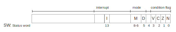
Fig. 5 Cpu0 status word (SW) register
When a CMP Ra, Rb instruction executes, it updates the condition flags in the status word (SW) register as follows:
If `Ra > Rb`, then N = 0, Z = 0
If `Ra < Rb`, then N = 1, Z = 0
If `Ra = Rb`, then N = 0, Z = 1
The direction (i.e., taken or not taken) of conditional jump instructions (JGT, JLT, JGE, JLE, JEQ, JNE) is determined by the values of the N and Z flags in the SW register.
Cpu0’s Stages of Instruction Execution
The Cpu0 architecture has a five-stage pipeline. The stages are: instruction fetch (IF), instruction decode (ID), execute (EX), memory access (MEM), and write-back (WB).
Below is a description of what happens in each stage of the processor:
Instruction Fetch (IF)
The Cpu0 fetches the instruction pointed to by the Program Counter (PC) into the Instruction Register (IR): IR = [PC].
The PC is then updated to point to the next instruction: PC = PC + 4.
Instruction Decode (ID)
The control unit decodes the instruction stored in IR, routes necessary data from registers to the ALU, and sets the ALU’s operation mode based on the instruction’s opcode.
Execute (EX)
The ALU executes the operation designated by the control unit on the data in registers.
Except for load and store instructions, the result is stored in the destination register after execution.
Memory Access (MEM)
If the instruction is a load, data is read from the data cache into the pipeline register MEM/WB.
If the instruction is a store, data is written from the register to the data cache.
Write-Back (WB)
If the instruction is a load, data is moved from the pipeline register MEM/WB to the destination register.
Cpu0’s Interrupt Vector
Address |
type |
|---|---|
0x00 |
Reset |
0x04 |
Error Handle |
0x08 |
Interrupt |
Clang
LLVM is middleware for compilers, with Clang as its frontend. The Clang project provides a language front-end and tooling infrastructure for languages in the C language family (C, C++, Objective C/C++, OpenCL, and CUDA) for the LLVM project.
Context Free Grammar
Definition:
“A context-free grammar defines a language that can be parsed independently of surrounding input context; each production rule applies based solely on the current nonterminal, not on neighboring symbols.”
All context-free grammars (CFGs) can be expressed in Backus-Naur Form (BNF).
Note
Computer languages have been adding complexity features for users’ programming:
☆ “(≈ 30 years ago) Programming languages are context‑free.” \(\Rightarrow\) “(Today) The syntax is context‑free, but the language is context‑sensitive.”
⚠️ 1. What older textbooks said
Textbooks from the 1980s–1990s typically taught:
“Programming languages are mostly context‑free.”
“Parsing is done with CFGs.”
“Semantic analysis comes later.”
They treated semantic constraints as a separate phase, not as part of the grammar
✅ 2. What modern textbooks say
Modern compiler books (e.g., newer editions of Aho/Ullman, Appel, Cooper/Torczon, Muchnick, and engineering‑oriented texts) now teach something closer to:
The surface syntax is context‑free.
Real languages require context-sensitive semantic analysis.
Some languages require semantic information during parsing (C++, Rust, Swift).
Macro systems and type inference break the clean CFG model.
They no longer pretend that a CFG fully describes a real language.
So the modern interpretation is:
“The grammar is context‑free, but the language is not.”
This is a subtle but important shift.
Statement |
Meaning |
How Modern Languages Changed |
|---|---|---|
Old Textbook Statement (≈ 30 years ago) “Programming languages are context‑free.” |
Focused only on the parser grammar. Treated semantic rules as a separate phase, not part of the language definition. |
Languages were simpler (C, Pascal, early C++). Few features required semantic feedback during parsing. Grammar-based teaching matched real compilers more closely. |
Modern Understanding (today) “The syntax is context‑free, but the language is context‑sensitive.” |
Parsing still uses a CFG, but real languages rely on name resolution, type inference, generics, macro expansion, and semantic disambiguation. |
Modern languages (C++, Rust, Swift, Kotlin, Go) require semantic information during parsing. Macro systems and type systems break pure CFG boundaries. Compilers use multi‑phase frontends to resolve context. |
Why doesn’t the Clang compiler use YACC/LEX tools to parse C++?
Clang does not use YACC/LEX because C++ is too complex and context-sensitive for traditional parser generators. YACC and LEX work with context-free grammars, but C++ has many context-sensitive features, especially in templates below:
Context-sensitive template instantiation
#include <iostream>

#if TEMPLATE==1
template <typename T>
void f(T x) {
    std::cout << "Template f(T)" << std::endl;
}
#endif

#if FUNCTION==1
void f(int x) {
    std::cout << "Non-template f(int)" << std::endl;
}
#endif

int main() {
#if (TEMPLATE==1) || (FUNCTION==1)
    f(42);        // Which one gets called?
    f('a');       // Template or non-template?
#endif
#if TEMPLATE==1
    f<int>('a');  // Explicit template instantiation
#endif
}
References % clang++ -DFUNCTION=1 -DTEMPLATE=0 cpp-template.cpp
References % ./a.out
Non-template f(int)
Non-template f(int)
References % clang++ -DFUNCTION=0 -DTEMPLATE=1 cpp-template.cpp
References % ./a.out
Template f(T)
Template f(T)
Template f(T)
References % clang++ -DFUNCTION=1 -DTEMPLATE=1 cpp-template.cpp
References % ./a.out
Non-template f(int)
Template f(T)
Template f(T)
In the C++ code above, both f(42) and f(‘a’) can match either the template function or the non-template function.
✅ Why This Is Hard for YACC:
YACC operates on context-free grammars, but this example is context-sensitive. The expression f(‘a’); selects a template if a template definition exists; otherwise, it selects a function if a function definition exists. As a result, this behavior cannot be implemented using BNF-based tools like YACC/LEX.
To parse this example, the following are required:
Template argument deduction: The compiler must infer T from the call.
Overload resolution: It must choose between the template and non-template versions.
Implicit conversions: ‘a’ can be converted to int, which affects overload ranking.
Explicit template instantiation: f<int>(‘a’) forces the template, but YACC doesn’t track template types.
To model this in YACC:
You’d need to simulate template instantiation and ranking — which is way beyond what YACC was designed for.
This kind of logic is not just syntactic — it’s deeply semantic. That’s why compilers like Clang use handwritten parsers with tight integration between parsing and semantic analysis.
Clang doesn’t use YACC/LEX because:
Feature |
YACC/LEX |
Hand-written Parser |
|---|---|---|
Handles context-sensitive grammar |
❌ |
✅ |
Good error recovery |
❌ |
✅ |
Integration with semantic analysis |
❌ |
✅ |
Easy to maintain/extend for C++ |
❌ |
✅ |
Fine-grained control |
❌ |
✅ |
The GNU g++ compiler abandoned BNF tools starting from version 3.x.
Compiler-Compiler Tools for Context-Sensitive C++ Parsing
While traditional tools like YACC/Lex are limited to context-free grammars, modern compiler construction requires handling context-sensitive features — especially in C++ templates, overload resolution, and semantic analysis. Below is a list of tools that attempt to address these challenges.
Tool |
Generates Parser Code? |
Context-Sensitive Support? |
Notes |
|---|---|---|---|
ANTLR |
✅ Yes |
⚠️ Limited |
Supports semantic predicates; struggles with full C++ complexity |
BNFLite |
✅ Yes |
⚠️ Partial |
Lightweight C++ template library; ideal for DSLs, not full C++ |
PEGTL |
✅ Yes |
⚠️ Limited |
PEG-based parser combinator library in C++; expressive but limited |
GLR Parsers (Elsa) |
✅ Yes |
✅ Yes |
Can handle ambiguity and deferred resolution; used in research |
Clang LibTooling |
✅ Yes (via AST) |
✅ Yes |
Offers full C++ parsing + semantic analysis; industrial-grade tooling |
Why Most Tools Fall Short:
C++ templates are Turing-complete, making static analysis alone insufficient.
Overload resolution requires understanding types, scopes, and conversions.
C++ syntax is deeply ambiguous, defying context-free parsing strategies.
Recommended Approach:
For building C++ parsers:
Use GLR-based tools like Elsa if ambiguity and template complexity must be handled directly.
Or leverage Clang LibTooling for full semantic integration, AST manipulation, and robust code analysis.
In summary, while modern tools improve on YACC/LEX, the complexity of C++ still requires a custom parser that deeply integrates with semantic analysis and type resolution. Clang’s approach remains the most practical for full C++ support. Moreover the error messages and recovery are still weaker than Clang.
While C++ compilers do not benefit from BNF generator tools, many other programming and scripting languages, which are more context-free, can take advantage of them. The following information comes from Wikipedia:
Java syntax has a context-free grammar that can be parsed by a simple LALR parser. Parsing C++ is more complicated [1].
Use metadata in LLVM
Key Aspects of the Clang Driver:
Driver vs. Frontend: When you run clang, you are using the driver. The driver calls the frontend, usually via clang -cc1.
GCC Compatibility: The clang driver is designed to be a drop-in replacement for the gcc driver, accepting similar command-line arguments.
Role: It manages high-level tasks like setting up include paths, selecting the target architecture, and determining which toolchain components to invoke.
The driver provides enhanced error reporting and efficient management of complex builds.
When running the same compiler executable twice concurrently, they run as separate processes, not as a single multi-threaded process.
Each time you launch the executable, the operating system creates a new process with its own memory space and resources. Even if both instances run at the same time, they remain independent of each other.
Within each process, the compiler may internally use multiple threads, but that does not change the fact that the two executions are separate processes.
Question (refined)
If each clang -cc1 runs in a separate process, will global variables or
static variables in LLVM still cause problems?
Answer
Yes — they can still cause problems, but in a different way.
Explanation
Since each clang -cc1 is a separate process:
Global/static variables are NOT shared across files
Each process has its own independent copy
So:
❌ No cross-file contamination
❌ No need to reset between
a.cppandb.cpp
However, problems can still occur within a single process.
—
What problems remain?
Within one translation unit (single cc1 process)
Even for one file:
LLVM runs many passes (IR → MIR → CodeGen)
Your global variable is shared across:
all functions
all passes
So:
State may unintentionally leak between functions
Order-dependent bugs can appear
—
Multi-threading inside one process
Even in one clang -cc1:
Some LLVM stages may use threads
Global variables then become:
❌ Race condition risks
❌ Non-deterministic results
—
Future changes (very important)
Your code may be correct today, but break later if:
LTO (Link Time Optimization) is enabled
ThinLTO merges modules
Clang runs multiple compilations in-process (tooling, JIT, etc.)
In those cases:
Global variables may be shared across modules
Bugs will reappear
—
Reentrancy and reuse issues
If LLVM is used as a library (e.g., JIT, tools):
Multiple compilations may happen in the same process
Global variables then:
Persist across compilations
Cause hidden state bugs
—
Key Insight
Multi-process (cc1) protects you from cross-file bugs,
but does NOT make global variables safe design.
—
Best Practice
Instead of globals:
Per-module → store in
Module(metadata / flags)Per-function → use
Function/MachineFunctionComplex state → use Analysis Pass
—
Summary
Separate
clang -cc1processes → isolate memory per fileBut global variables still: - Break modular design - Risk race conditions - Cause future scalability issues
✅ Safe today (in simple cases)
❌ Fragile and unsafe by design
LLVM Structure
This section introduces the compiler’s data structures, algorithms, and mechanisms used in LLVM.
SSA Form
Static Single Assignment (SSA) form ensures that each variable is assigned exactly once. In SSA form, a single instruction has one variable (destination virtual registers). However one virtual register may map to two real registers. LLVM handles it by packing them into a single value, like a struct or a vector, or using multiple instructions as follows:
%res = call {i32, i1} @llvm.sadd.with.overflow.i32(i32 %a, i32 %b)
%sum = extractvalue {i32, i1} %res, 0
%overflow = extractvalue {i32, i1} %res, 1
%y = call <4 x float> @llvm.ceil.v4f32(<4 x float> %x)
LLVM IR follows SSA form, meaning it has an unbounded number of virtual registers—each variable is assigned exactly once and is stored in a separate virtual register.
As a result, the optimization steps in the code generation sequence—including Instruction Selection, Scheduling and Formation, and Register Allocation—retain all optimization opportunities.
For example, if we used a limited number of virtual registers instead of an unlimited set, as shown in the following code:
%a = add nsw i32 1, i32 0
store i32 %a, i32* %c, align 4
%a = add nsw i32 2, i32 0
store i32 %a, i32* %c, align 4
In the above example, a limited number of virtual registers is used, causing virtual register %a to be assigned twice.
As a result, the compiler must generate the following code, since %a is assigned as an output in two different statements.
=> %a = add i32 1, i32 0
    st %a,  i32* %c, 1
    %a = add i32 2, i32 0
    st %a,  i32* %c, 2
The above code must execute sequentially.
In contrast, the SSA form shown below can be reordered and executed in parallel using the following alternative version [16].
  %a = add nsw i32 1, i32 0
  store i32 %a, i32* %c, align 4
  %b = add nsw i32 2, i32 0
  store i32 %b, i32* %d, align 4

// version 1
=> %a = add i32 1, i32 0
    st %a,  i32* %c, 0
    %b = add i32 2, i32 0
    st %b,  i32* %d, 0

// version 2
=> %a = add i32 1, i32 0
    %b = add i32 2, i32 0
    st %a,  i32* %c, 0
    st %b,  i32* %d, 0

// version 3
=> %b = add i32 2, i32 0
    st %b,  i32* %d, 0
    %a = add i32 1, i32 0
    st %a,  i32* %c, 0
DSA Form
for (int i = 0; i < 1000; i++) {
  b[i] = f(g(a[i]));
}
For the source program above, the following represent its SSA form at both the source code level and the LLVM IR level, respectively.
for (int i = 0; i < 1000; i++) {
  t = g(a[i]);
  b[i] = f(t);
}
  %pi = alloca i32
  store i32 0, i32* %pi
  %i = load i32, i32* %pi
  %cmp = icmp slt i32 %i, 1000
  br i1 %cmp, label %true, label %end
true:
  %a_idx = add i32 %i, i32 %a_addr
  %val0 = load i32, i32* %a_idx
  %t = call i64 %g(i32 %val0)
  %val1 = call i64 %f(i32 %t)
  %b_idx = add i32 %i, i32 %b_addr
  store i32 %val1, i32* %b_idx
end:
The following represents the DSA (Dynamic Single Assignment) form.
for (int i = 0; i < 1000; i++) {
  t[i] = g(a[i]);
  b[i] = f(t[i]);
}
  %pi = alloca i32
  store i32 0, i32* %pi
  %i = load i32, i32* %pi
  %cmp = icmp slt i32 %i, 1000
  br i1 %cmp, label %true, label %end
true:
  %a_idx = add i32 %i, i32 %a_addr
  %val0 = load i32, i32* %a_idx
  %t_idx = add i32 %i, i32 %t_addr
  %temp = call i64 %g(i32 %val0)
  store i32 %temp, i32* %t_idx
  %val1 = call i64 %f(i32 %temp)
  %b_idx = add i32 %i, i32 %b_addr
  store i32 %val1, i32* %b_idx
end:
In some internet video applications and multi-core (SMP) platforms, splitting g() and f() into two separate loops can improve performance.
DSA allows this transformation, whereas SSA does not. While extra analysis on %temp in SSA could reconstruct %t_idx and %t_addr as shown in the DSA form below, compiler transformations typically follow a high-to-low approach.
Additionally, LLVM IR already loses the for loop structure, even though part of the losted information can be reconstructed through further analysis.
For this reason, in this book—as well as in most compiler-related research—the discussion follows a high-to-low transformation premise. Otherwise, it would fall into the domain of reverse engineering in assemblers or compilers.
for (int i = 0; i < 1000; i++) {
  t[i] = g(a[i]);
}

for (int i = 0; i < 1000; i++) {
  b[i] = f(t[i]);
}
  %pi = alloca i32
  store i32 0, i32* %pi
  %i = load i32, i32* %pi
  %cmp = icmp slt i32 %i, 1000
  br i1 %cmp, label %true, label %end
true:
  %a_idx = add i32 %i, i32 %a_addr
  %val0 = load i32, i32* %a_idx
  %t_idx = add i32 %i, i32 %t_addr
  %temp = call i32 %g(i32 %val0)
  store i32 %temp, i32* %t_idx
end:

  %pi = alloca i32
  store i32 0, i32* %pi
  %i = load i32, i32* %pi
  %cmp = icmp slt i32 %i, 1000
  br i1 %cmp, label %true, label %end
true:
  %t_idx = add i32 %i, i32 %t_addr
  %temp = load i32, i32* %t_idx
  %val1 = call i32 %f(i32 %temp)
  %b_idx = add i32 %i, i32 %b_addr
  store i32 %val1, i32* %b_idx
end:
Now, data dependencies exist only on t[i] between “t[i] = g(a[i])” and “b[i] = f(t[i])” for each i = (0..999).
As a result, the program can execute in various orders, offering significant parallel processing opportunities for multi-core (SMP) systems and heterogeneous processors.
For example, g(x) can be executed on a GPU, while f(x) runs on a CPU.
Three-Phase Design
This content and the following sub-section are adapted from the AOSA chapter on LLVM written by Chris Lattner [10].
The most common design for a traditional static compiler (such as most C compilers) follows a three-phase structure, consisting of the front end, the optimizer, and the back end, as shown in Fig. 6.
The front end parses the source code, checks for errors, and constructs a language-specific Abstract Syntax Tree (AST) to represent the input code. The AST may then be converted into an intermediate representation for optimization, after which the optimizer and back end process the code.
![digraph CompilerPipeline {
rankdir=LR;
bgcolor="white";
node [fontname="Helvetica", fontsize=12];
// Invisible container for the three stages
subgraph cluster_compiler {
label="";
color="black";
penwidth=1.5;
style="rounded";
frontend [label="Frontend", shape=rectangle, style="filled", fillcolor="#e6f2ff"];
optimizer [label="Optimizer", shape=rectangle, style="filled", fillcolor="#e6f2ff"];
backend [label="Backend", shape=rectangle, style="filled", fillcolor="#e6f2ff"];
frontend -> optimizer -> backend [color="black"];
}
source [label="Source Code", shape=plaintext];
machine [label="Machine Code", shape=plaintext];
source -> frontend [label="", color="black"];
backend -> machine [label="", color="black"];
}](_images/graphviz-30414e59f090d384b8e45bceaea7238fdeca104d.png)
Fig. 6 Three Major Components of a Three Phase Compiler
The optimizer performs a wide range of transformations to improve code execution efficiency, such as eliminating redundant computations. It is generally independent of both the source language and the target architecture.
The back end, also known as the code generator, maps the optimized code onto the target instruction set. In addition to producing correct code, it is responsible for generating efficient code that leverages the unique features of the target architecture. Common components of a compiler back end include instruction selection, register allocation, and instruction scheduling.
This model applies equally well to interpreters and Just-In-Time (JIT) compilers. The Java Virtual Machine (JVM) is an example of this model, using Java bytecode as the interface between the front end and the optimizer.
The greatest advantage of this classical design becomes evident when a compiler supports multiple source languages or target architectures. If the compiler’s optimizer uses a common intermediate representation, a front end can be written for any language that compiles to this representation, and a back end can be developed for any target that compiles from it, as illustrated in Fig. 7.
![digraph ModularCompiler {
rankdir=LR;
bgcolor="white";
node [fontname="Helvetica", fontsize=12];
// Source languages
C [label="C Source", shape=plaintext];
Fortran [label="Fortran Source", shape=plaintext];
Ada [label="Ada Source", shape=plaintext];
// Frontends
C_FE [label="C Frontend"];
Fortran_FE [label="Fortran Frontend"];
Ada_FE [label="Ada Frontend"];
// Common optimizer
Optimizer [label="Common Optimizer", shape=rectangle, style="filled", fillcolor="#d9ead3"];
// Backends
X86_BE [label="X86 Backend"];
PPC_BE [label="PowerPC Backend"];
ARM_BE [label="ARM Backend"];
// Machine code outputs
X86_MC [label="X86 Machine Code", shape=plaintext];
PPC_MC [label="PowerPC Machine Code", shape=plaintext];
ARM_MC [label="ARM Machine Code", shape=plaintext];
// Connections
C -> C_FE;
Fortran -> Fortran_FE;
Ada -> Ada_FE;
C_FE -> Optimizer;
Fortran_FE -> Optimizer;
Ada_FE -> Optimizer;
Optimizer -> X86_BE;
Optimizer -> PPC_BE;
Optimizer -> ARM_BE;
X86_BE -> X86_MC;
PPC_BE -> PPC_MC;
ARM_BE -> ARM_MC;
}](_images/graphviz-a6bb41bda5b13ce3d628aebfc81e8f33594baee9.png)
Fig. 7 Retargetablity
With this design, porting the compiler to support a new source language (e.g., Algol or BASIC) requires implementing a new front end, while the existing optimizer and back end can be reused. If these components were not separated, adding a new source language would require rebuilding the entire compiler from scratch. Supporting N targets and M source languages would then necessitate developing N * M compilers.
Another advantage of the three-phase design, which stems from its retargetability, is that the compiler can serve a broader range of programmers compared to one that supports only a single source language and target. For an open-source project, this translates to a larger community of potential contributors, leading to more enhancements and improvements.
This is why open-source compilers that cater to diverse communities, such as GCC, often generate better-optimized machine code than narrower compilers like FreePASCAL. In contrast, the quality of proprietary compilers depends directly on their development budget. For example, the Intel ICC compiler is widely recognized for producing high-quality machine code despite serving a smaller audience.
A final major benefit of the three-phase design is that the skills required to develop a front end differ from those needed for the optimizer and back end. By separating these concerns, “front-end developers” can focus on enhancing and maintaining their part of the compiler. While this is a social rather than a technical factor, it has a significant impact in practice—especially for open-source projects aiming to lower barriers to contribution.
The most critical aspect of this design is the LLVM Intermediate Representation (IR), which serves as the compiler’s core code representation. LLVM IR is designed to support mid-level analysis and transformations commonly found in the optimization phase of a compiler.
It was created with several specific goals, including support for lightweight runtime optimizations, cross-function and interprocedural optimizations, whole- program analysis, and aggressive restructuring transformations. However, its most defining characteristic is that it is a first-class language with well- defined semantics.
To illustrate this, here is a simple example of an LLVM .ll file:
define i32 @add1(i32 %a, i32 %b) {
entry:
  %tmp1 = add i32 %a, %b
  ret i32 %tmp1
}
define i32 @add2(i32 %a, i32 %b) {
entry:
  %tmp1 = icmp eq i32 %a, 0
  br i1 %tmp1, label %done, label %recurse
recurse:
  %tmp2 = sub i32 %a, 1
  %tmp3 = add i32 %b, 1
  %tmp4 = call i32 @add2(i32 %tmp2, i32 %tmp3)
  ret i32 %tmp4
done:
  ret i32 %b
}
// Above LLVM IR corresponds to this C code, which provides two different ways to
//  add integers:
unsigned add1(unsigned a, unsigned b) {
  return a+b;
}
// Perhaps not the most efficient way to add two numbers.
unsigned add2(unsigned a, unsigned b) {
  if (a == 0) return b;
  return add2(a-1, b+1);
}
As shown in this example, LLVM IR is a low-level, RISC-like virtual instruction set. Like a real RISC instruction set, it supports linear sequences of simple instructions such as add, subtract, compare, and branch.
These instructions follow a three-address format, meaning they take inputs and produce a result in a different register. LLVM IR supports labels and generally resembles an unusual form of assembly language.
Unlike most RISC instruction sets, LLVM IR is strongly typed and uses a simple type system (e.g., i32 represents a 32-bit integer, and i32** is a pointer to a pointer to a 32-bit integer). Additionally, some machine-specific details are abstracted away.
For instance, the calling convention is handled through call and ret instructions with explicit arguments. Another key difference from machine code is that LLVM IR does not use a fixed set of named registers. Instead, it employs an infinite set of temporaries prefixed with %.
Beyond being a language, LLVM IR exists in three isomorphic forms:
A textual format (as seen above).
An in-memory data structure used by optimizations.
A compact binary “bitcode” format stored on disk.
The LLVM project provides tools to convert between these forms:
llvm-as assembles a textual .ll file into a .bc file containing bitcode.
llvm-dis disassembles a .bc file back into a .ll file.
The intermediate representation (IR) of a compiler is crucial because it creates an ideal environment for optimizations. Unlike the front end and back end, the optimizer is not restricted to a specific source language or target machine.
However, it must effectively serve both. It should be easy for the front end to generate while remaining expressive enough to enable important optimizations for real hardware targets.
LLVM’s Target Description Files: .td
The “mix and match” approach allows target authors to select components that best suit their architecture, enabling significant code reuse across different targets.
However, this introduces a challenge: each shared component must be capable of handling target-specific properties in a generic way. For instance, a shared register allocator must be aware of the register file of each target and the constraints that exist between instructions and their register operands.
LLVM addresses this challenge by requiring each target to provide a target description using a declarative domain-specific language, defined in a set of .td files. These files are processed by the tblgen tool to generate the necessary target-specific data structures.
The simplified build process for the x86 target is illustrated in Fig. 8.
![digraph TblgenFlow {
rankdir=LR;
bgcolor="white";
node [fontname="Helvetica", fontsize=12, style=filled, fillcolor="#e6f2ff"];
// Input .td files
InstrTD [label="X86InstrInfo.td"];
RegTD [label="X86RegisterInfo.td"];
ConvTD [label="X86CallingConv.td"];
// tblgen tool
Tblgen [label="tblgen Tool", shape=rectangle, style="filled", fillcolor="#f9cb9c"];
// Generated source files
InstrCPP [label="X86InstrInfo.cpp"];
RegCPP [label="X86RegisterInfo.cpp"];
FP_CPP [label="X86FloatingPoint.cpp"];
subgraph cluster_0 {
// Object files
label = "X86Target.a"
InstrOBJ [label="X86InstrInfo.o"];
RegOBJ [label="X86RegisterInfo.o"];
ConvOBJ [label="X86CallingConv.o"];
FP_OBJ [label="X86FloatingPoint.o"];
}
// Connections
InstrTD -> Tblgen;
RegTD -> Tblgen;
ConvTD -> Tblgen;
Tblgen -> InstrOBJ;
Tblgen -> RegOBJ;
Tblgen -> ConvOBJ;
InstrCPP -> InstrOBJ;
RegCPP -> RegOBJ;
ConvTD -> ConvOBJ;
FP_CPP -> FP_OBJ;
}](_images/graphviz-cc56c659e976275322d3304b964dad2cff0fdccb.png)
Fig. 8 Simplified x86 Target Definition
The different subsystems supported by .td files enable target authors to construct various components of their target architecture.
For example, the x86 backend defines a register class named “GR32”, which contains all 32-bit registers. In .td files, target-specific definitions are conventionally written in all capital letters. The definition is as follows:
def GR32 : RegisterClass<[i32], 32,
  [EAX, ECX, EDX, ESI, EDI, EBX, EBP, ESP,
   R8D, R9D, R10D, R11D, R14D, R15D, R12D, R13D]> { ... }
The language used in .td files is the Target (Hardware) Description Language, which allows LLVM backend compiler engineers to define the transformation from LLVM IR to machine instructions for their CPUs.
In the frontend, compiler development tools provide a Parser Generator for building compilers. In the backend, they offer a Machine Code Generator to facilitate instruction selection and code generation, as shown in Fig. 9 and Fig. 10.
![digraph G {
rankdir=TB;
subgraph cluster_0 {
node [color=black]; "parser generator such as yacc/lex";
node [shape=note]; "code gen function embedded in BNF", "regular expression + BNF", "front parser";
"code gen function embedded in BNF" -> "parser generator such as yacc/lex";
"regular expression + BNF" -> "parser generator such as yacc/lex";
"parser generator such as yacc/lex" -> "front parser";
}
subgraph cluster_1 {
node [color=black]; "yacc/lex";
node [shape=note]; "*.c, *.cpp", "*.y, *.l", "front parser: *.cpp";
"*.c, *.cpp" -> "yacc/lex";
"*.y, *.l" -> "yacc/lex";
"yacc/lex" -> "front parser: *.cpp";
}
// label = "Frontend TableGen Flow";
}](_images/graphviz-824f22988137941ae34a11c50a998397903414f6.png)
Fig. 9 Frontend TableGen Flow
![digraph G {
rankdir=TB;
subgraph cluster_0 {
node [color=black]; "TableGen";
node [shape=note]; "Hardware/Target Description Language Files", "Pattern Match files in c/c++\nfor IR -> Machine Instructions";
"Hardware/Target Description Language Files" -> "TableGen";
"TableGen" -> "Pattern Match files in c/c++\nfor IR -> Machine Instructions";
}
subgraph cluster_1 {
node [color=black]; "llvm-tblgen";
node [shape=note]; "*.td", "*.inc";
"*.td" -> "llvm-tblgen" -> "*.inc";
}
// label = "llvm TableGen Flow";
}](_images/graphviz-2d30ec2821e7ec43d245b55cad0844642bf266c4.png)
Fig. 10 llvm TableGen Flow
LLVM Code Generation Sequence
Following diagram is from tricore_llvm.pdf.
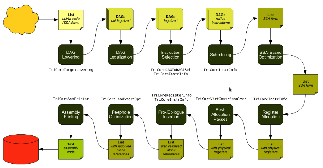
Fig. 11 tricore_llvm.pdf: Code Generation Sequence On the path from LLVM code to assembly code, numerous passes are executed, and several data structures are used to represent intermediate results.
LLVM is a Static Single Assignment (SSA)-based representation. It provides an infinite number of virtual registers that can hold values of primitive types, including integral, floating-point, and pointer values.
In LLVM’s SSA representation, each operand is stored in a separate virtual register. Comments in LLVM IR are denoted by the ; symbol.
The following are examples of LLVM SSA instructions:
store i32 0, i32* %a  ; store i32 type of 0 to virtual register %a, %a is
            ;  pointer type which point to i32 value
store i32 %b, i32* %c ; store %b contents to %c point to, %b isi32 type virtual
            ;  register, %c is pointer type which point to i32 value.
%a1 = load i32* %a    ; load the memory value where %a point to and assign the
            ;  memory value to %a1
%a3 = add i32 %a2, 1  ; add %a2 and 1 and save to %a3
We explain the code generation process below. If you are unfamiliar with the concepts, we recommend first reviewing Section 4.2 of tricore_llvm.pdf.
You may also refer to The LLVM Target-Independent Code Generator [12] and the LLVM Language Reference Manual [13]. However, we believe that Section 4.2 of tricore_llvm.pdf provides sufficient information.
We suggest consulting the above web documents only if you still have difficulties understanding the material, even after reading this section and the next two sections on DAG and Instruction Selection.
Instruction Selection
// In this stage, the LLVM opcode is transformed into a machine opcode,
// but the operand remains an LLVM virtual operand.
    store i16 0, i16* %a  // Store 0 of i16 type to the location pointed to by %a
=>  st i16 0, i32* %a     // Use the Cpu0 backend instruction `st` instead of `store`.
Scheduling and Formation
// In this stage, instruction order is optimized for execution cycles
// or to reduce register pressure.
    st i32 %a, i16* %b, i16 5  // Store %a to *(%b + 5)
    st %b, i32* %c, i16 0
    %d = ld i32* %c

// The instruction order is rearranged. In RISC CPUs like MIPS,
// `ld %c` depends on the previous `st %c`, requiring a 1-cycle delay.
// This means `ld` cannot immediately follow `st`.
=>  st %b, i32* %c, i16 0
    st i32 %a, i16* %b, i16 5
    %d = ld i32* %c, i16 0

// Without instruction reordering, a `nop` instruction must be inserted,
// adding an extra cycle. (In reality, MIPS dynamically schedules
// instructions and inserts `nop` between `st` and `ld` if necessary.)
    st i32 %a, i16* %b, i16 5
    st %b, i32* %c, i16 0
    nop
    %d = ld i32* %c, i16 0

// **Minimizing Register Pressure**
// Suppose `%c` remains live after the basic block, but `%a` and `%b` do not.
// Without reordering, at least 3 registers are required:
    %a = add i32 1, i32 0
    %b = add i32 2, i32 0
    st %a, i32* %c, 1
    st %b, i32* %c, 2

// The reordered version reduces register usage to 2 by allocating `%a`
// and `%b` in the same...

// Register allocation optimization
=> %a = add i32 1, i32 0
    st %a, i32* %c, 1
    %b = add i32 2, i32 0
    st %b, i32* %c, 2
SSA-Based Machine Code Optimization
For example, common subexpression elimination, as shown in the next section on DAG.
Register Allocation
Assign physical registers to virtual registers.
Prologue/Epilogue Code Insertion
Explained in the section Add Prologue/Epilogue Functions.
Late Machine Code Optimizations
Any “last-minute” peephole optimizations of the final machine code are applied in this phase. For example, replacing x = x * 2 with x = x << 1 for integer operands.
Code Emission
The final machine code is emitted. - For static compilation, the output is an assembly file. - For JIT compilation, machine instruction opcodes are written into memory.
The LLVM code generation sequence can also be viewed using:
llc -debug-pass=Structure
as shown below. The first four code generation stages from
Fig. 11 appear in the
‘DAG->DAG Pattern Instruction Selection’ section of the
llc -debug-pass=Structure output.
The order of Peephole Optimizations and Prologue/Epilogue Insertion
differs between Fig. 11 and
llc -debug-pass=Structure (marked with * in the output).
There is no need to be concerned about this, as LLVM is continuously evolving, and its internal sequence may change over time.
118-165-79-200:input Jonathan$ llc --help-hidden
OVERVIEW: llvm system compiler

USAGE: llc [options] <input bitcode>

OPTIONS:
...
  -debug-pass                             - Print PassManager debugging information
    =None                                 -   disable debug output
    =Arguments                            -   print pass arguments to pass to 'opt'
    =Structure                            -   print pass structure before run()
    =Executions                           -   print pass name before it is executed
    =Details                              -   print pass details when it is executed

118-165-79-200:input Jonathan$ llc -march=mips -debug-pass=Structure ch3.bc
...
Target Library Information
Target Transform Info
Data Layout
Target Pass Configuration
No Alias Analysis (always returns 'may' alias)
Type-Based Alias Analysis
Basic Alias Analysis (stateless AA impl)
Create Garbage Collector Module Metadata
Machine Module Information
Machine Branch Probability Analysis
  ModulePass Manager
    FunctionPass Manager
      Preliminary module verification
      Dominator Tree Construction
      Module Verifier
      Natural Loop Information
      Loop Pass Manager
        Canonicalize natural loops
      Scalar Evolution Analysis
      Loop Pass Manager
        Canonicalize natural loops
        Induction Variable Users
        Loop Strength Reduction
      Lower Garbage Collection Instructions
      Remove unreachable blocks from the CFG
      Exception handling preparation
      Optimize for code generation
      Insert stack protectors
      Preliminary module verification
      Dominator Tree Construction
      Module Verifier
      Machine Function Analysis
      Natural Loop Information
      Branch Probability Analysis
    * MIPS DAG->DAG Pattern Instruction Selection
      Expand ISel Pseudo-instructions
      Tail Duplication
      Optimize machine instruction PHIs
      MachineDominator Tree Construction
      Slot index numbering
      Merge disjoint stack slots
      Local Stack Slot Allocation
      Remove dead machine instructions
      MachineDominator Tree Construction
      Machine Natural Loop Construction
      Machine Loop Invariant Code Motion
      Machine Common Subexpression Elimination
      Machine code sinking
    * Peephole Optimizations
      Process Implicit Definitions
      Remove unreachable machine basic blocks
      Live Variable Analysis
      Eliminate PHI nodes for register allocation
      Two-Address instruction pass
      Slot index numbering
      Live Interval Analysis
      Debug Variable Analysis
      Simple Register Coalescing
      Live Stack Slot Analysis
      Calculate spill weights
      Virtual Register Map
      Live Register Matrix
      Bundle Machine CFG Edges
      Spill Code Placement Analysis
    * Greedy Register Allocator
      Virtual Register Rewriter
      Stack Slot Coloring
      Machine Loop Invariant Code Motion
    * Prologue/Epilogue Insertion & Frame Finalization
      Control Flow Optimizer
      Tail Duplication
      Machine Copy Propagation Pass
    * Post-RA pseudo instruction expansion pass
      MachineDominator Tree Construction
      Machine Natural Loop Construction
      Post RA top-down list latency scheduler
      Analyze Machine Code For Garbage Collection
      Machine Block Frequency Analysis
      Branch Probability Basic Block Placement
      Mips Delay Slot Filler
      Mips Long Branch
      MachineDominator Tree Construction
      Machine Natural Loop Construction
    * Mips Assembly Printer
      Delete Garbage Collector Information
Since Instruction Scheduling and Dead Code Elimination affect Register Allocation, LLVM does not revisit earlier passes once a later pass is completed. Register Allocation occurs after Instruction Scheduling.
The passes from Live Variable Analysis to Greedy Register Allocator handle Register Allocation. More details on register allocation passes can be found here: [14] [15].
LLVM vs. GCC in Structure
The official GCC documentation can be found here: [17].
frontend |
clang |
gcc-frontend [18] |
|---|---|---|
LANGUAGE |
C/C++ |
C/C++ |
parsing |
parsing |
parsing |
AST |
clang-AST |
GENERIC [19] |
optimization & codgen |
clang-backend |
gimplifier |
IR |
LLVM IR |
GIMPLE [20] |
backend |
llvm |
gcc |
|---|---|---|
IR |
LLVM IR |
GIMPLE |
transfer |
optimziation & pass |
optimization & plugins |
DAG |
DAG |
RTL [21] |
codgen |
tblgen for td |
codgen for md [22] |
Both LLVM IR and GIMPLE use SSA form.
LLVM IR was originally designed to be fully reusable across various tools, not just within the compiler itself. In contrast, the GCC community never intended for GIMPLE to be used beyond the compiler.
Richard Stallman actively resisted efforts to make GCC’s IR more reusable to prevent third-party commercial tools from leveraging GCC frontends. As a result, GIMPLE (GCC’s IR) was never designed to fully describe a compiled program.
For example, it lacks critical information such as the program’s call graph, type definitions, stack offsets, and alias information [23].
LLVM Blog
A user may rely on a null pointer as a guard to ensure code correctness. However, undef values occur only during compiler optimizations [24].
If a user fails to explicitly bind a null pointer—either directly or indirectly—compilers like LLVM and GCC may interpret the null pointer as undef, leading to unexpected optimization behavior [25].
CFG (Control Flow Graph)
The SSA form can be represented using a Control Flow Graph (CFG) and optimized by analyzing it.
Each node in the graph represents a basic block (BB)—a straight-line sequence of code without any jumps or jump targets. A jump target always starts a basic block, while a jump ends one [26].
The following is an example of a CFG. Jumps and branches always appear in the last statement of basic blocks (BBs) as shown in Fig. 12.
Fig/llvmstructure/cfg-ex.cpp
int cfg_ex(int a, int b, int n)
{
  for (int i = 0; i <= n; i++) {
    if (a < b) {
      a = a + i;
      b = b - 1;
    }
    if (b == 0) {
      goto label_1;
    }
  }

label_1:
  switch (a) {
  case 10:
    a = a*a-b+2;
    a++;
    break;
  }

  return (a+b);
}
Fig/llvmstructure/cfg-ex.ll
define dso_local i32 @_Z6cfg_exiii(i32 signext %a, i32 signext %b, i32 signext %n) local_unnamed_addr nounwind {
entry:
  %cmp.not23 = icmp slt i32 %n, 0
  br i1 %cmp.not23, label %cleanup, label %for.body

for.cond:                                         ; preds = %for.body
  %inc = add nuw i32 %i.026, 1
  %exitcond.not = icmp eq i32 %i.026, %n
  br i1 %exitcond.not, label %cleanup, label %for.body, !llvm.loop !2

for.body:                                         ; preds = %entry, %for.cond
  %i.026 = phi i32 [ %inc, %for.cond ], [ 0, %entry ]
  %a.addr.025 = phi i32 [ %a.addr.1, %for.cond ], [ %a, %entry ]
  %b.addr.024 = phi i32 [ %b.addr.1, %for.cond ], [ %b, %entry ]
  %cmp1 = icmp slt i32 %a.addr.025, %b.addr.024
  %sub = sext i1 %cmp1 to i32
  %b.addr.1 = add nsw i32 %b.addr.024, %sub
  %add = select i1 %cmp1, i32 %i.026, i32 0
  %a.addr.1 = add nsw i32 %add, %a.addr.025
  %cmp2 = icmp eq i32 %b.addr.1, 0
  br i1 %cmp2, label %cleanup, label %for.cond

cleanup:                                          ; preds = %for.cond, %for.body, %entry
  %b.addr.2 = phi i32 [ %b, %entry ], [ 0, %for.body ], [ %b.addr.1, %for.cond ]
  %a.addr.2 = phi i32 [ %a, %entry ], [ %a.addr.1, %for.body ], [ %a.addr.1, %for.cond ]
  %cond = icmp eq i32 %a.addr.2, 10
  %inc7 = sub i32 103, %b.addr.2
  %spec.select = select i1 %cond, i32 %inc7, i32 %a.addr.2
  %add8 = add nsw i32 %spec.select, %b.addr.2
  ret i32 %add8
}


!llvm.module.flags = !{!0}
!llvm.ident = !{!1}

!0 = !{i32 1, !"wchar_size", i32 4}
!1 = !{!"clang version 12.0.1"}
!2 = distinct !{!2, !3}
!3 = !{!"llvm.loop.mustprogress"}
![digraph "CFG for '_Z6cfg_exiii' function" {
label="CFG for '_Z6cfg_exiii' function";
Node0x600001b56240 [shape=record,color="#3d50c3ff", style=filled, fillcolor="#d6dce470",label="{entry:\l %cmp.not23 = icmp slt i32 %n, 0\l br i1 %cmp.not23, label %cleanup, label %for.body\l|{<s0>T|<s1>F}}"];
Node0x600001b56240:s0 -> Node0x600001b56280;
Node0x600001b56240:s1 -> Node0x600001b562c0;
Node0x600001b56300 [shape=record,color="#b70d28ff", style=filled, fillcolor="#bb1b2c70",label="{for.cond: \l %inc = add nuw i32 %i.026, 1\l %exitcond.not = icmp eq i32 %i.026, %n\l br i1 %exitcond.not, label %cleanup, label %for.body, !llvm.loop !2\l|{<s0>T|<s1>F}}"];
Node0x600001b56300:s0 -> Node0x600001b56280;
Node0x600001b56300:s1 -> Node0x600001b562c0;
Node0x600001b562c0 [shape=record,color="#b70d28ff", style=filled, fillcolor="#b70d2870",label="{for.body: \l %i.026 = phi i32 [ %inc, %for.cond ], [ 0, %entry ]\l %a.addr.025 = phi i32 [ %a.addr.1, %for.cond ], [ %a, %entry ]\l %b.addr.024 = phi i32 [ %b.addr.1, %for.cond ], [ %b, %entry ]\l %cmp1 = icmp slt i32 %a.addr.025, %b.addr.024\l %sub = sext i1 %cmp1 to i32\l %b.addr.1 = add nsw i32 %b.addr.024, %sub\l %add = select i1 %cmp1, i32 %i.026, i32 0\l %a.addr.1 = add nsw i32 %add, %a.addr.025\l %cmp2 = icmp eq i32 %b.addr.1, 0\l br i1 %cmp2, label %cleanup, label %for.cond\l|{<s0>T|<s1>F}}"];
Node0x600001b562c0:s0 -> Node0x600001b56280;
Node0x600001b562c0:s1 -> Node0x600001b56300;
Node0x600001b56280 [shape=record,color="#3d50c3ff", style=filled, fillcolor="#d6dce470",label="{cleanup: \l %b.addr.2 = phi i32 [ %b, %entry ], [ 0, %for.body ], [ %b.addr.1, %for.cond\l... ]\l %a.addr.2 = phi i32 [ %a, %entry ], [ %a.addr.1, %for.body ], [ %a.addr.1,\l... %for.cond ]\l %cond = icmp eq i32 %a.addr.2, 10\l %inc7 = sub i32 103, %b.addr.2\l %spec.select = select i1 %cond, i32 %inc7, i32 %a.addr.2\l %add8 = add nsw i32 %spec.select, %b.addr.2\l ret i32 %add8\l}"];
}](_images/graphviz-1ef8c202fab4f989ecaeec5682f87fc9beff5395.png)
Fig. 12 CFG for cfg-ex.ll
DAG (Directed Acyclic Graph)
The SSA form within each Basic Block (BB) from the Control Flow Graph (CFG), as discussed in the previous section, can be represented using a Directed Acyclic Graph (DAG).
Many key local optimization techniques begin by transforming a basic block into a DAG [27].
For example, the basic block code and its corresponding DAG are illustrated in Fig. 13.
![graph {
subgraph cluster_1
{
label = "a,d = b ediv c \nb = a - d \nc = b + c \nd = a - d";
A_c ;
A_c [label="c\n+"] ;
A_c -- A_bd ;
A_bd [label="b,d\n-"] ;
A_bd -- A_a ;
A_bd -- A_d0 ;
A_a [label="a", shape=none] ;
A_a -- A_ediv [style=dashed];
A_d0 [label="d0", shape=none] ;
A_d0 -- A_ediv [style=dashed];
A_ediv [label="ediv"] ;
A_ediv -- A_b0 ;
A_b0 [label="b0", shape=none] ;
A_ediv -- A_c0 ;
A_c0 [label="c0", shape=none] ;
A_c -- A_c0;
}
subgraph cluster_2
{
label = "a = b + c \nb = a - d \nc = b + c \nd = a - d";
B_c ;
B_c [label="c\n+"] ;
B_c -- B_bd ;
B_bd [label="b,d\n-"] ;
B_bd -- B_a ;
B_bd -- B_d0 ;
B_a [label="a\n+"] ;
B_d0 [label="d0", shape=none] ;
B_a -- B_b0 ;
B_b0 [label="b0", shape=none] ;
B_a -- B_c0 ;
B_c0 [label="c0", shape=none] ;
B_c -- B_c0;
}
}](_images/graphviz-713a5cde0536001a56c80fef342af43252d70089.png)
Fig. 13 The left example includes two destination registers, while the right has only one destination.
DAG and SSA allow instructions to have two destination virtual registers.
Assume the ediv operation performs integer division, storing the quotient in a and the remainder in d.
If only one destination register is used, the DAG may be simplified, as shown on the right in Fig. 13.
If b is not live at the exit of the block, we can apply common subexpression elimination, as demonstrated in the table below.
Replace node b with node d |
Replace b0, c0, d0 with b, c, d |
|---|---|
a = b0 + c0 |
a = b + c |
d = a – d0 |
d = a – d |
c = d + c |
c = d + c |
After removing b and traversing the DAG from bottom to top (using Depth-First In-Order Search in a binary tree), we obtain the first column of the table above.
As you can imagine, common subexpression elimination can be applied both at the IR level and in machine code.
A DAG resembles a tree where opcodes are nodes, and operands (registers, constants, immediates, or offsets) are leaves. It can also be represented as a prefix-ordered list in a tree structure. For example, (+ b, c) and (+ b, 1) are IR DAG representations.
In addition to DAG optimization, kill registers are discussed in Section 8.5.5 of the compiler book [27]. This optimization method is also applied in LLVM.
Instruction Selection
For machine instruction selection, the best approach is to represent both IR and machine instructions as a DAG.
To simplify visualization, register leaves are omitted in Fig. 14.
The expression rₖ + rⱼ represents an IR DAG (used as a symbolic notation, not in LLVM SSA form). ADD is the corresponding machine instruction.
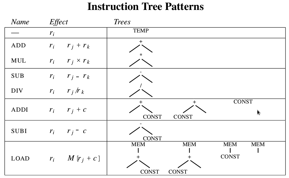
Fig. 14 Instruction DAG representation
The IR DAG and machine instruction DAG can also be represented as lists. For example:
IR DAG lists: (+ rᵢ, rⱼ) and (- rᵢ, 1)
Machine instruction DAG lists: (ADD rᵢ, rⱼ) and (SUBI rᵢ, 1)
Now, let’s examine the ADDiu instruction defined in Cpu0InstrInfo.td:
lbdex/chapters/Chapter2/Cpu0InstrFormats.td
//===----------------------------------------------------------------------===//
// Format L instruction class in Cpu0 : <|opcode|ra|rb|cx|>
//===----------------------------------------------------------------------===//

class FL<bits<8> op, dag outs, dag ins, string asmstr, list<dag> pattern,
         InstrItinClass itin>: Cpu0Inst<outs, ins, asmstr, pattern, itin, FrmL>
{
  bits<4>  ra;
  bits<4>  rb;
  bits<16> imm16;

  let Opcode = op;

  let Inst{23-20} = ra;
  let Inst{19-16} = rb;
  let Inst{15-0}  = imm16;
}
lbdex/chapters/Chapter2/Cpu0InstrInfo.td
// Node immediate fits as 16-bit sign extended on target immediate.
// e.g. addi, andi
def immSExt16  : PatLeaf<(imm), [{ return isInt<16>(N->getSExtValue()); }]>;
// Arithmetic and logical instructions with 2 register operands.
class ArithLogicI<bits<8> op, string instr_asm, SDNode OpNode,
                  Operand Od, PatLeaf imm_type, RegisterClass RC> :
  FL<op, (outs GPROut:$ra), (ins RC:$rb, Od:$imm16),
     !strconcat(instr_asm, "\t$ra, $rb, $imm16"),
     [(set GPROut:$ra, (OpNode RC:$rb, imm_type:$imm16))], IIAlu> {
  let isReMaterializable = 1;
}
// IR "add" defined in include/llvm/Target/TargetSelectionDAG.td, line 315 (def add).
def ADDiu   : ArithLogicI<0x09, "addiu", add, simm16, immSExt16, CPURegs>;
Fig. 15 illustrates how pattern matching works between the IR node add and the instruction node ADDiu, both defined in Cpu0InstrInfo.td.
In this example, the IR node “add %a, 5” is translated into “addiu $r1, 5” after %a is allocated to register $r1 during the register allocation stage.
This translation occurs because the IR pattern (set RC:$ra, (OpNode RC:$rb, imm_type:$imm16)) is defined for ADDiu, where the second operand is a signed immediate that matches %a, 5.
In addition to pattern matching, the .td file specifies the assembly mnemonic “addiu” and the opcode 0x09.
Using this information, LLVM TableGen automatically generates both assembly instructions and binary encodings. The resulting binary instruction can be included in an ELF object file, which will be explained in a later chapter.
Similarly, machine instruction DAG nodes LD and ST are translated from the IR DAG nodes load and store.
![digraph "DAG" {
rankdir="TB";
// label = "Figure: Pattern match for ADDiu instruction and IR node add in detail";
td [ penwidth = 1, fontname = "Courier New", shape = "rectangle", label =<<table border="0" cellborder="0" cellpadding="3" bgcolor="white">
<tr><td bgcolor="grey" align="center" colspan="2"><font color="white">Cpu0InstrInfo.td</font></td></tr>
<tr><td align="left" port="f0">def immSExt16 : PatLeaf<(imm), [{ return isInt<16>(N-<getSExtValue()); }]>;</td></tr>
<tr><td align="left">class ArithLogicI<bits<8> op, string instr_asm, SDNode OpNode</td></tr>
<tr><td align="left" port="f1"> Operand Od, PatLeaf imm_type, RegisterClass RC> </td></tr>
<tr><td align="left" port="f2"> FL<0op, (outs RC:$ra), (ins RC:$rb, Od:$imm16),</td></tr>
<tr><td align="left" port="f3"> !strconcat(instr_asm, "\t$ra, $rb, $imm16"),</td></tr>
<tr><td align="left" port="f4"> [(set RC:$ra, (OpNode RC:$rb, imm_type:$imm16))], IIAlu> {</td></tr>
<tr><td align="left" port="f5"> let isReMaterializable = 1;</td></tr>
<tr><td align="left">}</td></tr>
<tr><td align="left" port="f6">def ADDiu : ArithLogicI<0x09, "addiu", add, simm16, immSExt16, CPURegs>; </td></tr>
</table>> ];
a [shape=Mrecord,label="<aa>def ADDiu : ArithLogicI\<|<a0>0x09, |<a1>\"addiu\", |<a2>add, |<a3>simm16, |<a4>immSExt16, |<a5>CPURegs\>;"];
p [shape=Mrecord,label="<p8>RC:|<p9>$ra|<p0>OpNode|<p1>RC:|<p2>$rb|<p3>imm_type:|<p4>$imm16"];
q [shape=Mrecord,label="<q8>CPURegs:|<q9>$ra|<q0>add|<q1>CPURegs:|<q2>$rb|<q3>immSExt16:|<q4>$imm16"];
asm [shape=Mrecord,label="<asm0>\!strconcat\(|<asm1>instr_asm, \"\\t|<asm2>$ra, |<asm3>$rb, |<asm4>$imm16\)"];
mi [shape=Mrecord,label="<mi0>addiu|<mi1>$r2|<mi2>$r1|<mi3>5"];
td -> a;
td:f0:e -> q:q3 [label="%0 = add %a, 5 -- (5 is true for immSExt16, \nso pattern match for ADDiu succeed"];
a:a2 -> p:p0;
a:a5 -> p:p1;
a:a5 -> p:p8;
a:a4 -> p:p3;
td:f4:w -> p:w;
td:f3:w -> asm:w;
p:p0 -> q:q0;
p:p1 -> q:q1;
p:p8 -> q:q8;
p:p3 -> q:q3;
p:e -> q:e [label="expand pattern match rule"];
q:q0 -> asm:asm0;
q:q9 -> asm:asm1;
q:q2 -> asm:asm2;
q:q4 -> asm:asm4;
q:e -> asm:e [label="expand machine asm instruction"];
asm:asm1 -> mi:mi0 [label="addiu"];
asm:asm2 -> mi:mi1 [label="$r2"];
asm:asm3 -> mi:mi2 [label="$r1"];
asm:asm4 -> mi:mi3 [label="5"];
asm:e -> mi:e[label="When llvm assign $r2 as destination register, $r1 as source 0 register"];
}](_images/graphviz-91b4c1bb6868b3aacf78e25ab48564dd00501020.png)
Fig. 15 Detailed pattern matching for ADDiu instruction and IR node add
During DAG instruction selection, the leaf node must be a Data Node. ADDiu follows the L-type instruction format, requiring the last operand to fit within a 16-bit signed range.
To enforce this constraint, Cpu0InstrInfo.td defines a PatLeaf type immSExt16, allowing the LLVM system to recognize the valid operand range.
If the immediate value exceeds this range, “isInt<16>(N->getSExtValue())” returns false, and the `ADDiu` pattern is not selected during instruction selection.
Some CPUs and floating-point units (FPUs) include a multiply-and-add floating-point instruction, fmadd.
This instruction can be represented using a DAG list as follows: (fadd (fmul ra, rc), rb).
To implement this, we define the fmadd DAG pattern in the instruction .td file as shown below:
def FMADDS : AForm_1<59, 29,
          (ops F4RC:$FRT, F4RC:$FRA, F4RC:$FRC, F4RC:$FRB),
          "fmadds $FRT, $FRA, $FRC, $FRB",
          [(set F4RC:$FRT, (fadd (fmul F4RC:$FRA, F4RC:$FRC),
                       F4RC:$FRB))]>;
Similar to ADDiu, the pattern [(set F4RC:$FRT, (fadd (fmul F4RC:$FRA, F4RC:$FRC), F4RC:$FRB))] includes both fmul and fadd nodes.
Now, consider the following basic block notation IR and LLVM SSA IR code:
d = a * c
e = d + b
...
%d = fmul %a, %c
%e = fadd %d, %b
...
The Instruction Selection Process will translate these two IR DAG nodes:
(fmul %a, %c) (fadd %d, %b)
into a single machine instruction DAG node:
(`fmadd` %a, %c, %b)
instead of translating them into two separate machine instruction nodes (`fmul` and `fadd`).
This optimization occurs only if FMADDS appears before FMUL and FADD in your .td file.
%e = fmadd %a, %c, %b
...
As you can see, the IR notation representation is easier to read than the LLVM SSA IR form.
For this reason, this notation is occasionally used in this book.
Now, consider the following basic block code:
a = b + c   // in notation IR form
d = a – d
%e = fmadd %a, %c, %b // in llvm SSA IR form
We can apply Fig. 8 Instruction Tree Patterns to generate the following machine code:
load  rb, M(sp+8); // assume b allocate in sp+8, sp is stack point register
load  rc, M(sp+16);
add ra, rb, rc;
load  rd, M(sp+24);
sub rd, ra, rd;
fmadd re, ra, rc, rb;
Caller and Callee Saved Registers
lbdex/input/ch9_caller_callee_save_registers.cpp
extern int add1(int x);

int callee()
{
  int t1 = 3;
  int result = add1(t1);
  result = result - t1;

  return result;
}
Running the MIPS backend with the above input will produce the following result:
JonathantekiiMac:input Jonathan$ ~/llvm/debug/build/bin/llc
-O0 -march=mips -relocation-model=static -filetype=asm
ch9_caller_callee_save_registers.bc -o -
      .text
      .abicalls
      .option pic0
      .section        .mdebug.abi32,"",@progbits
      .nan    legacy
      .file   "ch9_caller_callee_save_registers.bc"
      .text
      .globl  _Z6calleev
      .align  2
      .type   _Z6calleev,@function
      .set    nomicromips
      .set    nomips16
      .ent    _Z6calleev
_Z6callerv:                             # @_Z6callerv
      .cfi_startproc
      .frame  $fp,32,$ra
      .mask   0xc0000000,-4
      .fmask  0x00000000,0
      .set    noreorder
      .set    nomacro
      .set    noat
# BB#0:
      addiu   $sp, $sp, -32
$tmp0:
      .cfi_def_cfa_offset 32
      sw      $ra, 28($sp)            # 4-byte Folded Spill
      sw      $fp, 24($sp)            # 4-byte Folded Spill
$tmp1:
      .cfi_offset 31, -4
$tmp2:
      .cfi_offset 30, -8
      move     $fp, $sp
$tmp3:
      .cfi_def_cfa_register 30
      addiu   $1, $zero, 3
      sw      $1, 20($fp)   # store t1 to 20($fp)
      move     $4, $1
      jal     _Z4add1i
      nop
      sw      $2, 16($fp)   # $2 : the return vaule for fuction add1()
      lw      $1, 20($fp)   # load t1 from 20($fp)
      subu    $1, $2, $1
      sw      $1, 16($fp)
      move     $2, $1     # move result to return register $2
      move     $sp, $fp
      lw      $fp, 24($sp)            # 4-byte Folded Reload
      lw      $ra, 28($sp)            # 4-byte Folded Reload
      addiu   $sp, $sp, 32
      jr      $ra
      nop
      .set    at
      .set    macro
      .set    reorder
      .end    _Z6calleev
$func_end0:
      .size   _Z6calleev, ($func_end0)-_Z6calleev
      .cfi_endproc
Caller and callee saved registers definition as follows,
If the caller wants to use caller-saved registers after calling a function, it must save their contents to memory before the function call and restore them afterward.
If the callee wants to use callee-saved registers, it must save their contents to memory before using them and restore them before returning.
According to the definition above, if a register is not callee-saved, then it must be caller-saved, since the callee does not restore it and its value may change after the function call.
Thus, MIPS only defines callee-saved registers in MipsCallingConv.td, which can be found in CSR_O32_SaveList of MipsGenRegisterInfo.inc for the default ABI.
From the assembly output, MIPS allocates the t1 variable to register $1, which does not need to be spilled because $1 is a caller-saved register.
On the other hand, $ra is a callee-saved register, so it is spilled at the beginning of the assembly output, as jal uses the $ra register.
For Cpu0, the $lr register corresponds to MIPS $ra. Thus, the function setAliasRegs(MF, SavedRegs, Cpu0::LR) is called in determineCalleeSaves() within Cpu0SEFrameLowering.cpp when a function calls another function.
Live-In and Live-Out Registers
As seen in the previous subsection, $ra is a live-in register because the return address is determined by the caller.
Similarly, $2 is a live-out register since the function’s return value is stored in this register. The caller retrieves the result by reading $2 directly, as noted in the previous example.
By marking live-in and live-out registers, the backend provides LLVM’s middle layer with information to eliminate redundant variable access instructions.
LLVM applies DAG analysis, as discussed in the previous subsection, to perform this optimization.
Since C supports separate compilation, the live-in and live-out information from the backend offers additional optimization opportunities to LLVM.
LLVM provides the function addLiveIn() to mark a live-in register, but it does not offer a corresponding addLiveOut() function.
Instead, the MIPS backend marks live-out registers by using:
DAG = DAG.getCopyToReg(…, $2, …)
and then returning the modified DAG, as all local variables cease to exist after the function exits.
Create Cpu0 Backend
From this point onward, the Cpu0 backend will be created step by step from scratch.
To help readers understand the backend structure, the Cpu0 example code can be generated chapter by chapter using the command provided here [11].
The Cpu0 example code (`lbdex`) can be found near the bottom left of this website or downloaded from:
http://jonathan2251.github.io/lbd/lbdex.tar.gz
Cpu0 Backend Machine ID and Relocation Records
To create a new backend, several files in <<llvm root dir>> must be modified.
The required modifications include adding both the machine ID and name, as well as defining relocation records.
The ELF Support chapter provides an introduction to relocation records.
The following files are modified to add the Cpu0 backend:
lbdex/llvm/modify/llvm/config-ix.cmake
...
elseif (LLVM_NATIVE_ARCH MATCHES "cpu0")
  set(LLVM_NATIVE_ARCH Cpu0)
...
lbdex/llvm/modify/llvm/CMakeLists.txt
set(LLVM_ALL_TARGETS
  ...
  Cpu0
  ...
  )
lbdex/llvm/modify/llvm/include/llvm/ADT/Triple.h
...
#undef mips
#undef cpu0
...
class Triple {
public:
  enum ArchType {
    ...
    cpu0,       // For Tutorial Backend Cpu0
    cpu0el,
    ...
  };
  ...
}
lbdex/llvm/modify/llvm/include/llvm/Object/ELFObjectFile.h
...
template <class ELFT>
StringRef ELFObjectFile<ELFT>::getFileFormatName() const {
  switch (EF.getHeader()->e_ident[ELF::EI_CLASS]) {
  case ELF::ELFCLASS32:
    switch (EF.getHeader()->e_machine) {
    ...
    case ELF::EM_CPU0:        // llvm-objdump -t -r
      return "ELF32-cpu0";
    ...
  }
  ...
}
...
template <class ELFT>
unsigned ELFObjectFile<ELFT>::getArch() const {
  bool IsLittleEndian = ELFT::TargetEndianness == support::little;
  switch (EF.getHeader()->e_machine) {
  ...
  case ELF::EM_CPU0:  // llvm-objdump -t -r
    switch (EF.getHeader()->e_ident[ELF::EI_CLASS]) {
    case ELF::ELFCLASS32:
    return IsLittleEndian ? Triple::cpu0el : Triple::cpu0;
    default:
      report_fatal_error("Invalid ELFCLASS!");
    }
  ...
  }
}
lbdex/llvm/modify/llvm/include/llvm/Support/ELF.h
enum {
  ...
  EM_CPU0          = 999  // Document LLVM Backend Tutorial Cpu0
};
...
// Cpu0 Specific e_flags
enum {
  EF_CPU0_NOREORDER = 0x00000001, // Don't reorder instructions
  EF_CPU0_PIC       = 0x00000002, // Position independent code
  EF_CPU0_ARCH_32   = 0x50000000, // CPU032 instruction set per linux not elf.h
  EF_CPU0_ARCH      = 0xf0000000  // Mask for applying EF_CPU0_ARCH_ variant
};

// ELF Relocation types for Mips
enum {
#include "ELFRelocs/Cpu0.def"
};
...
lbdex/llvm/modify/llvm/lib/MC/MCSubtargetInfo.cpp
bool Cpu0DisableUnreconginizedMessage = false;

void MCSubtargetInfo::InitMCProcessorInfo(StringRef CPU, StringRef FS) {
  #if 1 // Disable reconginized processor message. For Cpu0
  if (TargetTriple.getArch() == llvm::Triple::cpu0 ||
      TargetTriple.getArch() == llvm::Triple::cpu0el)
    Cpu0DisableUnreconginizedMessage = true;
  #endif
  ...
}
...
const MCSchedModel &MCSubtargetInfo::getSchedModelForCPU(StringRef CPU) const {
  ...
    #if 1 // Disable reconginized processor message. For Cpu0
    if (TargetTriple.getArch() != llvm::Triple::cpu0 &&
        TargetTriple.getArch() != llvm::Triple::cpu0el)
    #endif
  ...
}
lbdex/llvm/modify/llvm/lib/MC/SubtargetFeature.cpp
extern bool Cpu0DisableUnreconginizedMessage; // For Cpu0
...
FeatureBitset
SubtargetFeatures::ToggleFeature(FeatureBitset Bits, StringRef Feature,
                                 ArrayRef<SubtargetFeatureKV> FeatureTable) {
  ...
    if (!Cpu0DisableUnreconginizedMessage) // For Cpu0
  ...
}

FeatureBitset
SubtargetFeatures::ApplyFeatureFlag(FeatureBitset Bits, StringRef Feature,
                                    ArrayRef<SubtargetFeatureKV> FeatureTable) {
  ...
    if (!Cpu0DisableUnreconginizedMessage) // For Cpu0
  ...
}

FeatureBitset
SubtargetFeatures::getFeatureBits(StringRef CPU,
                                  ArrayRef<SubtargetFeatureKV> CPUTable,
                                  ArrayRef<SubtargetFeatureKV> FeatureTable) {
  ...
    if (!Cpu0DisableUnreconginizedMessage) // For Cpu0
  ...
}
lib/object/ELF.cpp
...

StringRef getELFRelocationTypeName(uint32_t Machine, uint32_t Type) {
  switch (Machine) {
  ...
  case ELF::EM_CPU0:
    switch (Type) {
#include "llvm/Support/ELFRelocs/Cpu0.def"
    default:
      break;
    }
    break;
  ...
  }
include/llvm/Support/ELFRelocs/Cpu0.def
#ifndef ELF_RELOC
#error "ELF_RELOC must be defined"
#endif

ELF_RELOC(R_CPU0_NONE,                0)
ELF_RELOC(R_CPU0_32,                  2)
ELF_RELOC(R_CPU0_HI16,                5)
ELF_RELOC(R_CPU0_LO16,                6)
ELF_RELOC(R_CPU0_GPREL16,             7)
ELF_RELOC(R_CPU0_LITERAL,             8)
ELF_RELOC(R_CPU0_GOT16,               9)
ELF_RELOC(R_CPU0_PC16,               10)
ELF_RELOC(R_CPU0_CALL16,             11)
ELF_RELOC(R_CPU0_GPREL32,            12)
ELF_RELOC(R_CPU0_PC24,               13)
ELF_RELOC(R_CPU0_GOT_HI16,           22)
ELF_RELOC(R_CPU0_GOT_LO16,           23)
ELF_RELOC(R_CPU0_RELGOT,             36)
ELF_RELOC(R_CPU0_TLS_GD,             42)
ELF_RELOC(R_CPU0_TLS_LDM,            43)
ELF_RELOC(R_CPU0_TLS_DTP_HI16,       44)
ELF_RELOC(R_CPU0_TLS_DTP_LO16,       45)
ELF_RELOC(R_CPU0_TLS_GOTTPREL,       46)
ELF_RELOC(R_CPU0_TLS_TPREL32,        47)
ELF_RELOC(R_CPU0_TLS_TP_HI16,        49)
ELF_RELOC(R_CPU0_TLS_TP_LO16,        50)
ELF_RELOC(R_CPU0_GLOB_DAT,           51)
ELF_RELOC(R_CPU0_JUMP_SLOT,          127)
lbdex/llvm/modify/llvm/lib/Support/Triple.cpp
const char *Triple::getArchTypeName(ArchType Kind) {
  switch (Kind) {
  ...
  case cpu0:        return "cpu0";
  case cpu0el:      return "cpu0el";
  ...
  }
}
...
const char *Triple::getArchTypePrefix(ArchType Kind) {
  switch (Kind) {
  ...
  case cpu0:
  case cpu0el:      return "cpu0";
  ...
}
...
Triple::ArchType Triple::getArchTypeForLLVMName(StringRef Name) {
  return StringSwitch<Triple::ArchType>(Name)
    ...
    .Case("cpu0", cpu0)
    .Case("cpu0el", cpu0el)
    ...
}
...
static Triple::ArchType parseArch(StringRef ArchName) {
  return StringSwitch<Triple::ArchType>(ArchName)
    ...
    .Cases("cpu0", "cpu0eb", "cpu0allegrex", Triple::cpu0)
    .Cases("cpu0el", "cpu0allegrexel", Triple::cpu0el)
    ...
}
...
static Triple::ObjectFormatType getDefaultFormat(const Triple &T) {
  ...
  case Triple::cpu0:
  case Triple::cpu0el:
  ...
}
...
static unsigned getArchPointerBitWidth(llvm::Triple::ArchType Arch) {
  switch (Arch) {
  ...
  case llvm::Triple::cpu0:
  case llvm::Triple::cpu0el:
  ...
    return 32;
  }
}
...
Triple Triple::get32BitArchVariant() const {
  Triple T(*this);
  switch (getArch()) {
  ...
  case Triple::cpu0:
  case Triple::cpu0el:
  ...
    // Already 32-bit.
    break;
  }
  return T;
}
Creating the Initial Cpu0 .td Files
As discussed in the previous section, LLVM uses target description files (.td files) to define various components of a target’s backend.
For example, these .td files may describe: - A target’s register set - Its instruction set - Instruction scheduling details - Calling conventions
When the backend is compiled, LLVM’s TableGen tool translates these .td files into C++ source code, which is then written to .inc files.
For more details on how to use TableGen, please refer to [32].
Each backend has its own .td files to define target-specific information. These files have a C++-like syntax.
For Cpu0, the primary target description file is Cpu0Other.td, as shown below:
lbdex/chapters/Chapter2/Cpu0.td
//===-- Cpu0.td - Describe the Cpu0 Target Machine ---------*- tablegen -*-===//
//
//                     The LLVM Compiler Infrastructure
//
// This file is distributed under the University of Illinois Open Source
// License. See LICENSE.TXT for details.
//
//===----------------------------------------------------------------------===//

// Without this will have error: 'cpu032I' is not a recognized processor for
//  this target (ignoring processor)
//===----------------------------------------------------------------------===//
// Cpu0 Subtarget features                                                    //
//===----------------------------------------------------------------------===//

def FeatureChapter3_1  : SubtargetFeature<"ch3_1", "HasChapterDummy", "true",
                                "Enable Chapter instructions.">;
def FeatureChapter3_2  : SubtargetFeature<"ch3_2", "HasChapterDummy", "true",
                                "Enable Chapter instructions.">;
def FeatureChapter3_3  : SubtargetFeature<"ch3_3", "HasChapterDummy", "true",
                                "Enable Chapter instructions.">;
def FeatureChapter3_4  : SubtargetFeature<"ch3_4", "HasChapterDummy", "true",
                                "Enable Chapter instructions.">;
def FeatureChapter3_5  : SubtargetFeature<"ch3_5", "HasChapterDummy", "true",
                                "Enable Chapter instructions.">;
def FeatureChapter4_1  : SubtargetFeature<"ch4_1", "HasChapterDummy", "true",
                                "Enable Chapter instructions.">;
def FeatureChapter4_2  : SubtargetFeature<"ch4_2", "HasChapterDummy", "true",
                                "Enable Chapter instructions.">;
def FeatureChapter5_1  : SubtargetFeature<"ch5_1", "HasChapterDummy", "true",
                                "Enable Chapter instructions.">;
def FeatureChapter6_1  : SubtargetFeature<"ch6_1", "HasChapterDummy", "true",
                                "Enable Chapter instructions.">;
def FeatureChapter7_1  : SubtargetFeature<"ch7_1", "HasChapterDummy", "true",
                                "Enable Chapter instructions.">;
def FeatureChapter8_1  : SubtargetFeature<"ch8_1", "HasChapterDummy", "true",
                                "Enable Chapter instructions.">;
def FeatureChapter8_2  : SubtargetFeature<"ch8_2", "HasChapterDummy", "true",
                                "Enable Chapter instructions.">;
def FeatureChapter9_1  : SubtargetFeature<"ch9_1", "HasChapterDummy", "true",
                                "Enable Chapter instructions.">;
def FeatureChapter9_2  : SubtargetFeature<"ch9_2", "HasChapterDummy", "true",
                                "Enable Chapter instructions.">;
def FeatureChapter9_3  : SubtargetFeature<"ch9_3", "HasChapterDummy", "true",
                                "Enable Chapter instructions.">;
def FeatureChapter10_1 : SubtargetFeature<"ch10_1", "HasChapterDummy", "true",
                                "Enable Chapter instructions.">;
def FeatureChapter11_1 : SubtargetFeature<"ch11_1", "HasChapterDummy", "true",
                                "Enable Chapter instructions.">;
def FeatureChapter11_2 : SubtargetFeature<"ch11_2", "HasChapterDummy", "true",
                                "Enable Chapter instructions.">;
def FeatureChapter12_1 : SubtargetFeature<"ch12_1", "HasChapterDummy", "true",
                                "Enable Chapter instructions.">;
def FeatureChapterAll  : SubtargetFeature<"chall", "HasChapterDummy", "true",
                                "Enable Chapter instructions.",
                                [FeatureChapter3_1, FeatureChapter3_2,
                                 FeatureChapter3_3, FeatureChapter3_4,
                                 FeatureChapter3_5,
                                 FeatureChapter4_1, FeatureChapter4_2,
                                 FeatureChapter5_1, FeatureChapter6_1,
                                 FeatureChapter7_1, FeatureChapter8_1,
                                 FeatureChapter8_2, FeatureChapter9_1,
                                 FeatureChapter9_2, FeatureChapter9_3,
                                 FeatureChapter10_1,
                                 FeatureChapter11_1, FeatureChapter11_2,
                                 FeatureChapter12_1]>;

def FeatureCmp         : SubtargetFeature<"cmp", "HasCmp", "true",
                                "Enable 'cmp' instructions.">;
def FeatureSlt         : SubtargetFeature<"slt", "HasSlt", "true",
                                "Enable 'slt' instructions.">;
def FeatureCpu032I     : SubtargetFeature<"cpu032I", "Cpu0ArchVersion",
                                "Cpu032I", "Cpu032I ISA Support",
                                [FeatureCmp, FeatureChapterAll]>;
def FeatureCpu032II    : SubtargetFeature<"cpu032II", "Cpu0ArchVersion",
                               "Cpu032II", "Cpu032II ISA Support (slt)",
                                [FeatureCmp, FeatureSlt, FeatureChapterAll]>;

//===----------------------------------------------------------------------===//
// Calling Conv, Instruction Descriptions
//===----------------------------------------------------------------------===//

include "Cpu0Schedule.td"
include "Cpu0InstrInfo.td"

def Cpu0InstrInfo : InstrInfo;
//===----------------------------------------------------------------------===//
// Cpu0 processors supported.
//===----------------------------------------------------------------------===//

class Proc<string Name, list<SubtargetFeature> Features>
 : Processor<Name, Cpu0GenericItineraries, Features>;

def : Proc<"cpu032I",  [FeatureCpu032I]>;
def : Proc<"cpu032II", [FeatureCpu032II]>;
// Above make Cpu0GenSubtargetInfo.inc set feature bit as the following order
// enum {
//   FeatureCmp =  1ULL << 0,
//   FeatureCpu032I =  1ULL << 1,
//   FeatureCpu032II =  1ULL << 2,
//   FeatureSlt =  1ULL << 3
// };

// Will generate Cpu0GenAsmWrite.inc included by Cpu0InstPrinter.cpp, contents
//  as follows,
// void Cpu0InstPrinter::printInstruction(const MCInst *MI, raw_ostream &O) {...}
// const char *Cpu0InstPrinter::getRegisterName(unsigned RegNo) {...}
def Cpu0 : Target {
// def Cpu0InstrInfo : InstrInfo as before.
  let InstructionSet = Cpu0InstrInfo;
}
lbdex/chapters/Chapter2/Cpu0Other.td
//===-- Cpu0Other.td - Describe the Cpu0 Target Machine ----*- tablegen -*-===//
//
//                     The LLVM Compiler Infrastructure
//
// This file is distributed under the University of Illinois Open Source
// License. See LICENSE.TXT for details.
//
//===----------------------------------------------------------------------===//
// This is the top level entry point for the Cpu0 target.
//===----------------------------------------------------------------------===//

//===----------------------------------------------------------------------===//
// Target-independent interfaces
//===----------------------------------------------------------------------===//

include "llvm/Target/Target.td"

//===----------------------------------------------------------------------===//
// Target-dependent interfaces
//===----------------------------------------------------------------------===//

include "Cpu0RegisterInfo.td"
include "Cpu0RegisterInfoGPROutForOther.td" // except AsmParser
include "Cpu0.td"
Cpu0Other.td and Cpu0.td include several other .td files.
Cpu0RegisterInfo.td (shown below) describes the Cpu0 register set.
In this file, each register is assigned a name. For example, `def PC` defines a register named PC.
In addition to register definitions, this file also defines register classes. A target may have multiple register classes, such as: - CPURegs - SR - C0Regs - GPROut
The GPROut register class, defined in Cpu0RegisterInfoGPROutForOther.td, includes all CPURegs except SW, ensuring that SW is not allocated as an output register during the register allocation stage.
lbdex/chapters/Chapter2/Cpu0RegisterInfo.td
//===-- Cpu0RegisterInfo.td - Cpu0 Register defs -----------*- tablegen -*-===//
//
//                     The LLVM Compiler Infrastructure
//
// This file is distributed under the University of Illinois Open Source
// License. See LICENSE.TXT for details.
//
//===----------------------------------------------------------------------===//

//===----------------------------------------------------------------------===//
//  Declarations that describe the CPU0 register file
//===----------------------------------------------------------------------===//

// We have banks of 16 registers each.
class Cpu0Reg<bits<16> Enc, string n> : Register<n> {
  // For tablegen(... -gen-emitter)  in CMakeLists.txt
  let HWEncoding = Enc;

  let Namespace = "Cpu0";
}

// Cpu0 CPU Registers
class Cpu0GPRReg<bits<16> Enc, string n> : Cpu0Reg<Enc, n>;

// Co-processor 0 Registers
class Cpu0C0Reg<bits<16> Enc, string n> : Cpu0Reg<Enc, n>;

//===----------------------------------------------------------------------===//
//@Registers
//===----------------------------------------------------------------------===//
// The register string, such as "9" or "gp" will show on "llvm-objdump -d"
//@ All registers definition
let Namespace = "Cpu0" in {
  //@ General Purpose Registers
  def ZERO : Cpu0GPRReg<0,  "zero">, DwarfRegNum<[0]>;
  def AT   : Cpu0GPRReg<1,  "1">,    DwarfRegNum<[1]>;
  def V0   : Cpu0GPRReg<2,  "2">,    DwarfRegNum<[2]>;
  def V1   : Cpu0GPRReg<3,  "3">,    DwarfRegNum<[3]>;
  def A0   : Cpu0GPRReg<4,  "4">,    DwarfRegNum<[4]>;
  def A1   : Cpu0GPRReg<5,  "5">,    DwarfRegNum<[5]>;
  def T9   : Cpu0GPRReg<6,  "t9">,   DwarfRegNum<[6]>;
  def T0   : Cpu0GPRReg<7,  "7">,    DwarfRegNum<[7]>;
  def T1   : Cpu0GPRReg<8,  "8">,    DwarfRegNum<[8]>;
  def S0   : Cpu0GPRReg<9,  "9">,    DwarfRegNum<[9]>;
  def S1   : Cpu0GPRReg<10, "10">,   DwarfRegNum<[10]>;
  def GP   : Cpu0GPRReg<11, "gp">,   DwarfRegNum<[11]>;
  def FP   : Cpu0GPRReg<12, "fp">,   DwarfRegNum<[12]>;
  def SP   : Cpu0GPRReg<13, "sp">,   DwarfRegNum<[13]>;
  def LR   : Cpu0GPRReg<14, "lr">,   DwarfRegNum<[14]>;
  def SW   : Cpu0GPRReg<15, "sw">,   DwarfRegNum<[15]>;
//  def MAR  : Register< 16, "mar">,  DwarfRegNum<[16]>;
//  def MDR  : Register< 17, "mdr">,  DwarfRegNum<[17]>;

  def PC   : Cpu0C0Reg<0, "pc">,  DwarfRegNum<[20]>;
  def EPC  : Cpu0C0Reg<1, "epc">, DwarfRegNum<[21]>;
}

//===----------------------------------------------------------------------===//
//@Register Classes
//===----------------------------------------------------------------------===//

def CPURegs : RegisterClass<"Cpu0", [i32], 32, (add
  // Reserved
  ZERO, AT,
  // Return Values and Arguments
  V0, V1, A0, A1,
  // Not preserved across procedure calls
  T9, T0, T1,
  // Callee save
  S0, S1,
  // Reserved
  GP, FP,
  SP, LR, SW)>;

//@Status Registers class
def SR     : RegisterClass<"Cpu0", [i32], 32, (add SW)>;

//@Co-processor 0 Registers class
def C0Regs : RegisterClass<"Cpu0", [i32], 32, (add PC, EPC)>;
lbdex/chapters/Chapter2/Cpu0RegisterInfoGPROutForOther.td
//===----------------------------------------------------------------------===//
// Register Classes
//===----------------------------------------------------------------------===//

def GPROut : RegisterClass<"Cpu0", [i32], 32, (add (sub CPURegs, SW))>;
In C++, a class typically defines a structure to organize data and functions, while definitions allocate memory for specific instances of the class.
For example:
class Date {  // declare Date
  int year, month, day;
};
Date birthday;  // define birthday, an instance of Date
The class Date has the members year, month, and day, but these do not yet belong to an actual object.
By defining an instance of Date called birthday, memory is allocated for a specific object, allowing you to set its year, month, and day.
In .td files, a class describes the structure of how data is laid out, while definitions act as specific instances of the class.
If you refer back to the Cpu0RegisterInfo.td file, you will see a class called Cpu0Reg, which is derived from the Register class provided by LLVM. Cpu0Reg inherits all fields from the Register class.
The statement “let HWEncoding = Enc” assigns the field HWEncoding from the parameter Enc.
Since Cpu0 reserves 4 bits for 16 registers in its instruction format, the assigned value range is 0 to 15.
Once values between 0 and 15 are assigned to HWEncoding, the backend register number is determined using LLVM’s register class functions, as TableGen automatically sets this number.
The `def` keyword is used to create instances of a class.
In the following line, the ZERO register is defined as a member of the Cpu0GPRReg class:
def ZERO : Cpu0GPRReg< 0, "ZERO">, DwarfRegNum<[0]>;
The def ZERO statement defines the name of this register. The parameters <0, “ZERO”> are used to create this specific instance of the Cpu0GPRReg class.
Thus, the field Enc is set to 0, and the string n is set to “ZERO”.
Since this register exists in the Cpu0 namespace, it can be referenced in the backend C++ code using Cpu0::ZERO.
### Overriding Values with let Expressions
The `let` expressions allow overriding values initially defined in a superclass.
For example, `let Namespace = “Cpu0”` in the Cpu0Reg class overrides the default namespace declared in the Register class.
Additionally, Cpu0RegisterInfo.td defines CPURegs as an instance of the RegisterClass, a built-in LLVM class.
A RegisterClass is essentially a set of Register instances, so CPURegs can be described as a set of registers.
### Cpu0 Instruction Definition
The Cpu0 instruction description file is named Cpu0InstrInfo.td. Its contents are as follows:
lbdex/chapters/Chapter2/Cpu0InstrInfo.td
//===- Cpu0InstrInfo.td - Target Description for Cpu0 Target -*- tablegen -*-=//
//
//                     The LLVM Compiler Infrastructure
//
// This file is distributed under the University of Illinois Open Source
// License. See LICENSE.TXT for details.
//
//===----------------------------------------------------------------------===//
//
// This file contains the Cpu0 implementation of the TargetInstrInfo class.
//
//===----------------------------------------------------------------------===//

//===----------------------------------------------------------------------===//
// Cpu0 profiles and nodes
//===----------------------------------------------------------------------===//

def SDT_Cpu0Ret          : SDTypeProfile<0, 1, [SDTCisInt<0>]>;

// Return
def Cpu0Ret : SDNode<"Cpu0ISD::Ret", SDTNone,
                     [SDNPHasChain, SDNPOptInGlue, SDNPVariadic]>;

//===----------------------------------------------------------------------===//
// Instruction format superclass
//===----------------------------------------------------------------------===//

include "Cpu0InstrFormats.td"

//===----------------------------------------------------------------------===//
// Cpu0 Operand, Complex Patterns and Transformations Definitions.
//===----------------------------------------------------------------------===//
// Instruction operand types

// Signed Operand
def simm16      : Operand<i32> {
  let DecoderMethod= "DecodeSimm16";
}

// Address operand
def mem : Operand<iPTR> {
  let PrintMethod = "printMemOperand";
  let MIOperandInfo = (ops GPROut, simm16);
  let EncoderMethod = "getMemEncoding";
}

// Node immediate fits as 16-bit sign extended on target immediate.
// e.g. addi, andi
def immSExt16  : PatLeaf<(imm), [{ return isInt<16>(N->getSExtValue()); }]>;

// Cpu0 Address Mode! SDNode frameindex could possibily be a match
// since load and store instructions from stack used it.
def addr :
  ComplexPattern<iPTR, 2, "SelectAddr", [frameindex], [SDNPWantParent]>;

//===----------------------------------------------------------------------===//
// Pattern fragment for load/store
//===----------------------------------------------------------------------===//

class AlignedLoad<PatFrag Node> :
  PatFrag<(ops node:$ptr), (Node node:$ptr), [{
  LoadSDNode *LD = cast<LoadSDNode>(N);
  return LD->getMemoryVT().getSizeInBits()/8 <= LD->getAlignment();
}]>;

class AlignedStore<PatFrag Node> :
  PatFrag<(ops node:$val, node:$ptr), (Node node:$val, node:$ptr), [{
  StoreSDNode *SD = cast<StoreSDNode>(N);
  return SD->getMemoryVT().getSizeInBits()/8 <= SD->getAlignment();
}]>;

// Load/Store PatFrags.
def load_a          : AlignedLoad<load>;
def store_a         : AlignedStore<store>;

//===----------------------------------------------------------------------===//
// Instructions specific format
//===----------------------------------------------------------------------===//

// Arithmetic and logical instructions with 2 register operands.
class ArithLogicI<bits<8> op, string instr_asm, SDNode OpNode,
                  Operand Od, PatLeaf imm_type, RegisterClass RC> :
  FL<op, (outs GPROut:$ra), (ins RC:$rb, Od:$imm16),
     !strconcat(instr_asm, "\t$ra, $rb, $imm16"),
     [(set GPROut:$ra, (OpNode RC:$rb, imm_type:$imm16))], IIAlu> {
  let isReMaterializable = 1;
}

class FMem<bits<8> op, dag outs, dag ins, string asmstr, list<dag> pattern,
          InstrItinClass itin>: FL<op, outs, ins, asmstr, pattern, itin> {
  bits<20> addr;
  let Inst{19-16} = addr{19-16};
  let Inst{15-0}  = addr{15-0};
  let DecoderMethod = "DecodeMem";
}

// Memory Load/Store
let canFoldAsLoad = 1 in
class LoadM<bits<8> op, string instr_asm, PatFrag OpNode, RegisterClass RC,
            Operand MemOpnd, bit Pseudo>:
  FMem<op, (outs RC:$ra), (ins MemOpnd:$addr),
     !strconcat(instr_asm, "\t$ra, $addr"),
     [(set RC:$ra, (OpNode addr:$addr))], IILoad> {
  let isPseudo = Pseudo;
}

class StoreM<bits<8> op, string instr_asm, PatFrag OpNode, RegisterClass RC,
             Operand MemOpnd, bit Pseudo>:
  FMem<op, (outs), (ins RC:$ra, MemOpnd:$addr),
     !strconcat(instr_asm, "\t$ra, $addr"),
     [(OpNode RC:$ra, addr:$addr)], IIStore> {
  let isPseudo = Pseudo;
}

//@ 32-bit load.
class LoadM32<bits<8> op, string instr_asm, PatFrag OpNode,
                   bit Pseudo = 0>
  : LoadM<op, instr_asm, OpNode, GPROut, mem, Pseudo> {
}

// 32-bit store.
class StoreM32<bits<8> op, string instr_asm, PatFrag OpNode,
                    bit Pseudo = 0>
  : StoreM<op, instr_asm, OpNode, GPROut, mem, Pseudo> {
}

//@JumpFR {
let isBranch=1, isTerminator=1, isBarrier=1, imm16=0, hasDelaySlot = 1,
    isIndirectBranch = 1 in
class JumpFR<bits<8> op, string instr_asm, RegisterClass RC>:
  FL<op, (outs), (ins RC:$ra),
     !strconcat(instr_asm, "\t$ra"), [(brind RC:$ra)], IIBranch> {
  let rb = 0;
  let imm16 = 0;
}
//@JumpFR }

// Return instruction
class RetBase<RegisterClass RC>: JumpFR<0x3c, "ret", RC> {
  let isReturn = 1;
  let isCodeGenOnly = 1;
  let hasCtrlDep = 1;
  let hasExtraSrcRegAllocReq = 1;
}


//===----------------------------------------------------------------------===//
// Instruction definition
//===----------------------------------------------------------------------===//

//===----------------------------------------------------------------------===//
// Cpu0 Instructions
//===----------------------------------------------------------------------===//

/// Load and Store Instructions
///  aligned
def LD     : LoadM32<0x01,  "ld",  load_a>;
def ST     : StoreM32<0x02, "st",  store_a>;

/// Arithmetic Instructions (ALU Immediate)
// IR "add" defined in include/llvm/Target/TargetSelectionDAG.td, line 315 (def add).
def ADDiu   : ArithLogicI<0x09, "addiu", add, simm16, immSExt16, CPURegs>;

/// Arithmetic Instructions (3-Operand, R-Type)

/// Shift Instructions

def JR      : JumpFR<0x3c, "jr", GPROut>;

def RET     : RetBase<GPROut>;

/// No operation
let addr=0 in
  def NOP   : FJ<0, (outs), (ins), "nop", [], IIAlu>;

//===----------------------------------------------------------------------===//
//  Arbitrary patterns that map to one or more instructions
//===----------------------------------------------------------------------===//

// Small immediates
def : Pat<(i32 immSExt16:$in),
          (ADDiu ZERO, imm:$in)>;
The Cpu0InstrFormats.td file is included in Cpu0InstrInfo.td, as shown:
lbdex/chapters/Chapter2/Cpu0InstrFormats.td
//===-- Cpu0InstrFormats.td - Cpu0 Instruction Formats -----*- tablegen -*-===//
//
//                     The LLVM Compiler Infrastructure
//
// This file is distributed under the University of Illinois Open Source
// License. See LICENSE.TXT for details.
//
//===----------------------------------------------------------------------===//

//===----------------------------------------------------------------------===//
//  Describe CPU0 instructions format
//
//  CPU INSTRUCTION FORMATS
//
//  opcode  - operation code.
//  ra      - dst reg, only used on 3 regs instr.
//  rb      - src reg.
//  rc      - src reg (on a 3 reg instr).
//  cx      - immediate
//
//===----------------------------------------------------------------------===//

// Format specifies the encoding used by the instruction.  This is part of the
// ad-hoc solution used to emit machine instruction encodings by our machine
// code emitter.
class Format<bits<4> val> {
  bits<4> Value = val;
}

def Pseudo    : Format<0>;
def FrmA      : Format<1>;
def FrmL      : Format<2>;
def FrmJ      : Format<3>;
def FrmOther  : Format<4>; // Instruction w/ a custom format

// Generic Cpu0 Format
class Cpu0Inst<dag outs, dag ins, string asmstr, list<dag> pattern,
               InstrItinClass itin, Format f>: Instruction
{
  // Inst and Size: for tablegen(... -gen-emitter) and
  // tablegen(... -gen-disassembler) in CMakeLists.txt
  field bits<32> Inst;
  Format Form = f;

  let Namespace = "Cpu0";

  let Size = 4;

  bits<8> Opcode = 0;

  // Top 8 bits are the 'opcode' field
  let Inst{31-24} = Opcode;

  let OutOperandList = outs;
  let InOperandList  = ins;

  let AsmString   = asmstr;
  let Pattern     = pattern;
  let Itinerary   = itin;

  //
  // Attributes specific to Cpu0 instructions...
  //
  bits<4> FormBits = Form.Value;

  // TSFlags layout should be kept in sync with Cpu0InstrInfo.h.
  let TSFlags{3-0}   = FormBits;

  let DecoderNamespace = "Cpu0";

  field bits<32> SoftFail = 0;
}

//===----------------------------------------------------------------------===//
// Format A instruction class in Cpu0 : <|opcode|ra|rb|rc|cx|>
//===----------------------------------------------------------------------===//

class FA<bits<8> op, dag outs, dag ins, string asmstr,
         list<dag> pattern, InstrItinClass itin>:
      Cpu0Inst<outs, ins, asmstr, pattern, itin, FrmA>
{
  bits<4>  ra;
  bits<4>  rb;
  bits<4>  rc;
  bits<12> shamt;

  let Opcode = op;

  let Inst{23-20} = ra;
  let Inst{19-16} = rb;
  let Inst{15-12} = rc;
  let Inst{11-0}  = shamt;
}

//@class FL {
//===----------------------------------------------------------------------===//
// Format L instruction class in Cpu0 : <|opcode|ra|rb|cx|>
//===----------------------------------------------------------------------===//

class FL<bits<8> op, dag outs, dag ins, string asmstr, list<dag> pattern,
         InstrItinClass itin>: Cpu0Inst<outs, ins, asmstr, pattern, itin, FrmL>
{
  bits<4>  ra;
  bits<4>  rb;
  bits<16> imm16;

  let Opcode = op;

  let Inst{23-20} = ra;
  let Inst{19-16} = rb;
  let Inst{15-0}  = imm16;
}
//@class FL }

//===----------------------------------------------------------------------===//
// Format J instruction class in Cpu0 : <|opcode|address|>
//===----------------------------------------------------------------------===//

class FJ<bits<8> op, dag outs, dag ins, string asmstr, list<dag> pattern,
         InstrItinClass itin>: Cpu0Inst<outs, ins, asmstr, pattern, itin, FrmJ>
{
  bits<24> addr;

  let Opcode = op;

  let Inst{23-0} = addr;
}
### Expanding ADDiu
ADDiu is an instance of the ArithLogicI class, which inherits from FL. It can be further expanded to retrieve its member values as follows:
def ADDiu   : ArithLogicI<0x09, "addiu", add, simm16, immSExt16, CPURegs>;

/// Arithmetic and logical instructions with 2 register operands.
class ArithLogicI<bits<8> op, string instr_asm, SDNode OpNode,
          Operand Od, PatLeaf imm_type, RegisterClass RC> :
  FL<op, (outs GPROut:$ra), (ins RC:$rb, Od:$imm16),
   !strconcat(instr_asm, "\t$ra, $rb, $imm16"),
   [(set GPROut:$ra, (OpNode RC:$rb, imm_type:$imm16))], IIAlu> {
  let isReMaterializable = 1;
}
So,
op = 0x09
instr_asm = "addiu"
OpNode = add
Od = simm16
imm_type = immSExt16
RC = CPURegs
### Expanding .td Files: Key Principles
`let`: Overrides an existing field from the parent class.
Example: let isReMaterializable = 1; This overrides isReMaterializable from the Instruction class in Target.td.
Declaration: Defines a new field for the class.
Example: bits<4> ra; This declares the ra field in the FL class.
### ADDiu Expansion Details
The details of expansion are shown in the following table:
ADDiu |
ArithLogicI |
FL |
|---|---|---|
0x09 |
op = 0x09 |
Opcode = 0x09; |
addiu |
instr_asm = “addiu” |
(outs GPROut:$ra); !strconcat(“addiu”, “t$ra, $rb, $imm16”); |
add |
OpNode = add |
[(set GPROut:$ra, (add CPURegs:$rb, immSExt16:$imm16))] |
simm16 |
Od = simm16 |
(ins CPURegs:$rb, simm16:$imm16); |
immSExt16 |
imm_type = immSExt16 |
Inst{15-0} = imm16; |
CPURegs |
RC = CPURegs isReMaterializable=1; |
Inst{23-20} = ra; Inst{19-16} = rb; |
Cpu0Inst |
instruction |
|---|---|
Namespace = “Cpu0” |
Uses = []; … |
Inst{31-24} = 0x09; |
Size = 0; … |
OutOperandList = GPROut:$ra; |
|
InOperandList = CPURegs:$rb,simm16:$imm16; |
|
AsmString = “addiut$ra, $rb, $imm16” |
|
pattern = [(set GPROut:$ra, (add RC:$rb, immSExt16:$imm16))] |
|
Itinerary = IIAlu |
|
TSFlags{3-0} = FrmL.value |
|
DecoderNamespace = “Cpu0” |
The .td file expansion process can be cumbersome. Similarly, LD and ST instruction definitions can be expanded in the same manner.
Note the Pattern:
[(set GPROut:$ra, (add RC:$rb, immSExt16:$imm16))]
which includes the keyword “add”.
The ADDiu instruction with “add” was used in the Instruction Selection subsection of the previous section.
### Cpu0 Scheduling Information
The Cpu0Schedule.td file includes details about function units and pipeline stages, as shown below:
lbdex/chapters/Chapter2/Cpu0Schedule.td
//===-- Cpu0Schedule.td - Cpu0 Scheduling Definitions ------*- tablegen -*-===//
//
//                     The LLVM Compiler Infrastructure
//
// This file is distributed under the University of Illinois Open Source
// License. See LICENSE.TXT for details.
//
//===----------------------------------------------------------------------===//

//===----------------------------------------------------------------------===//
// Functional units across Cpu0 chips sets. Based on GCC/Cpu0 backend files.
//===----------------------------------------------------------------------===//
def ALU     : FuncUnit;
def IMULDIV : FuncUnit;

//===----------------------------------------------------------------------===//
// Instruction Itinerary classes used for Cpu0
//===----------------------------------------------------------------------===//
def IIAlu              : InstrItinClass;
def II_CLO             : InstrItinClass;
def II_CLZ             : InstrItinClass;
def IILoad             : InstrItinClass;
def IIStore            : InstrItinClass;
def IIBranch           : InstrItinClass;

def IIPseudo           : InstrItinClass;

//===----------------------------------------------------------------------===//
// Cpu0 Generic instruction itineraries.
//===----------------------------------------------------------------------===//
//@ http://llvm.org/docs/doxygen/html/structllvm_1_1InstrStage.html
def Cpu0GenericItineraries : ProcessorItineraries<[ALU, IMULDIV], [], [
//@2
  InstrItinData<IIAlu              , [InstrStage<1,  [ALU]>]>,
  InstrItinData<II_CLO             , [InstrStage<1,  [ALU]>]>,
  InstrItinData<II_CLZ             , [InstrStage<1,  [ALU]>]>,
  InstrItinData<IILoad             , [InstrStage<3,  [ALU]>]>,
  InstrItinData<IIStore            , [InstrStage<1,  [ALU]>]>,
  InstrItinData<IIBranch           , [InstrStage<1,  [ALU]>]>
]>;
### Writing the CMake File
The Target/Cpu0 directory contains the CMakeLists.txt file. Its contents are as follows:
lbdex/chapters/Chapter2/CMakeLists.txt
add_llvm_component_group(Cpu0)

set(LLVM_TARGET_DEFINITIONS Cpu0Other.td)

# Generate Cpu0GenRegisterInfo.inc and Cpu0GenInstrInfo.inc which included by
#  your hand code C++ files.
# Cpu0GenRegisterInfo.inc came from Cpu0RegisterInfo.td, Cpu0GenInstrInfo.inc
#  came from Cpu0InstrInfo.td.
tablegen(LLVM Cpu0GenRegisterInfo.inc -gen-register-info)
tablegen(LLVM Cpu0GenInstrInfo.inc -gen-instr-info)
tablegen(LLVM Cpu0GenSubtargetInfo.inc -gen-subtarget)
tablegen(LLVM Cpu0GenMCPseudoLowering.inc -gen-pseudo-lowering)

# Cpu0CommonTableGen must be defined
add_public_tablegen_target(Cpu0CommonTableGen)

# Cpu0CodeGen should match with LLVMBuild.txt Cpu0CodeGen
add_llvm_target(Cpu0CodeGen
  Cpu0TargetMachine.cpp

  LINK_COMPONENTS
  Analysis
  AsmPrinter
  CodeGen
  Core
  MC
  Cpu0Desc
  Cpu0Info
  SelectionDAG
  Support
  Target
  GlobalISel

  ADD_TO_COMPONENT
  Cpu0
  )

# Should match with "subdirectories =  MCTargetDesc TargetInfo" in LLVMBuild.txt
add_subdirectory(TargetInfo)
add_subdirectory(MCTargetDesc)
CMakeLists.txt provides build instructions for CMake. Comments in this file are prefixed with #.
The “tablegen(” function in CMakeLists.txt is defined in:
cmake/modules/TableGen.cmake
as shown below:
llvm/cmake/modules/TableGen.cmake
function(tablegen project ofn)
  ...
  add_custom_command(OUTPUT ${CMAKE_CURRENT_BINARY_DIR}/${ofn}.tmp
    # Generate tablegen output in a temporary file.
    COMMAND ${${project}_TABLEGEN_EXE} ${ARGN} -I ${CMAKE_CURRENT_SOURCE_DIR}
  ...
endfunction()
...
macro(add_tablegen target project)
  ...
  if(LLVM_USE_HOST_TOOLS)
    if( ${${project}_TABLEGEN} STREQUAL "${target}" )
      if (NOT CMAKE_CONFIGURATION_TYPES)
        set(${project}_TABLEGEN_EXE "${LLVM_NATIVE_BUILD}/bin/${target}")
      else()
        set(${project}_TABLEGEN_EXE "${LLVM_NATIVE_BUILD}/Release/bin/${target}")
      endif()
  ...
endmacro()
llvm/utils/TableGen/CMakeLists.txt
add_tablegen(llvm-tblgen LLVM
  ...
)
The “add_tablegen” function in llvm/utils/TableGen/CMakeLists.txt makes “tablegen(” in Cpu0 CMakeLists.txt an alias for llvm-tblgen (where ${project} = LLVM and ${project}_TABLEGEN_EXE = llvm-tblgen).
The following elements define the Cpu0CommonTableGen target, which generates the output files Cpu0Gen*.inc:
“tablegen(”
“add_public_tablegen_target(Cpu0CommonTableGen)”
The following additional code
llvm/cmake/modules/TableGen.cmake
function(tablegen project ofn)
  ...
  set(TABLEGEN_OUTPUT ${TABLEGEN_OUTPUT} ${CMAKE_CURRENT_BINARY_DIR}/${ofn} PARENT_SCOPE)
  ...
endfunction()

# Creates a target for publicly exporting tablegen dependencies.
function(add_public_tablegen_target target)
  ...
  add_custom_target(${target}
    DEPENDS ${TABLEGEN_OUTPUT})
  ...
endfunction()
Since the llvm-tblgen executable is built before compiling any LLVM backend source code, it is always available to handle TableGen requests during the build process.
This book introduces backend source code incrementally, adding code chapter by chapter based on function.
### Understanding Source Code
Don’t try to understand everything from the text alone— the code added in each chapter serves as learning material too.
Conceptual understanding of computer-related knowledge can be gained without reading source code.
However, when implementing based on existing open-source software, reading source code is essential.
Documentation cannot fully replace source code in programming.
Reading source code is a valuable skill in open-source development.
### CMakeLists.txt in Subdirectories
The CMakeLists.txt files exist in the MCTargetDesc and TargetInfo subdirectories.
These files instruct LLVM to generate the Cpu0Desc and Cpu0Info libraries, respectively.
After building, you will find three libraries in the lib/ directory of your build folder:
libLLVMCpu0CodeGen.a
libLLVMCpu0Desc.a
libLLVMCpu0Info.a
For more details, refer to “Building LLVM with CMake” [28].
Target Registration
You must register your target with the TargetRegistry. After registration, LLVM tools can identify and use your target at runtime.
Although the TargetRegistry can be used directly, most targets utilize helper templates to simplify the process.
All targets should declare a global Target object, which represents the target during registration.
Then, in the target’s TargetInfo library, the target should define this object and use the RegisterTarget template to register it.
For example, the file TargetInfo/Cpu0TargetInfo.cpp registers TheCpu0Target for big-endian and TheCpu0elTarget for little-endian, as shown below:
lbdex/chapters/Chapter2/Cpu0.h
//===-- Cpu0.h - Top-level interface for Cpu0 representation ----*- C++ -*-===//
//
//                     The LLVM Compiler Infrastructure
//
// This file is distributed under the University of Illinois Open Source
// License. See LICENSE.TXT for details.
//
//===----------------------------------------------------------------------===//
//
// This file contains the entry points for global functions defined in
// the LLVM Cpu0 back-end.
//
//===----------------------------------------------------------------------===//

#ifndef LLVM_LIB_TARGET_CPU0_CPU0_H
#define LLVM_LIB_TARGET_CPU0_CPU0_H

#include "Cpu0Config.h"
#include "MCTargetDesc/Cpu0MCTargetDesc.h"
#include "llvm/Target/TargetMachine.h"

namespace llvm {
  class Cpu0TargetMachine;
  class FunctionPass;

} // end namespace llvm;

#endif
lbdex/chapters/Chapter2/TargetInfo/Cpu0TargetInfo.cpp
//===-- Cpu0TargetInfo.cpp - Cpu0 Target Implementation -------------------===//
//
//                     The LLVM Compiler Infrastructure
//
// This file is distributed under the University of Illinois Open Source
// License. See LICENSE.TXT for details.
//
//===----------------------------------------------------------------------===//

#include "Cpu0.h"
#include "llvm/IR/Module.h"
#include "llvm/Support/TargetRegistry.h"
using namespace llvm;

Target llvm::TheCpu0Target, llvm::TheCpu0elTarget;

extern "C" void LLVMInitializeCpu0TargetInfo() {
  RegisterTarget<Triple::cpu0,
        /*HasJIT=*/true> X(TheCpu0Target, "cpu0", "CPU0 (32-bit big endian)", "Cpu0");

  RegisterTarget<Triple::cpu0el,
        /*HasJIT=*/true> Y(TheCpu0elTarget, "cpu0el", "CPU0 (32-bit little endian)", "Cpu0");
}
lbdex/chapters/Chapter2/TargetInfo/CMakeLists.txt
# llvm 10.0.0 change from add_llvm_library to add_llvm_component_library
add_llvm_component_library(LLVMCpu0Info
  Cpu0TargetInfo.cpp

  LINK_COMPONENTS
  Support

  ADD_TO_COMPONENT
  Cpu0
  )
The files Cpu0TargetMachine.cpp and MCTargetDesc/Cpu0MCTargetDesc.cpp currently define only an empty initialization function, as no components are being registered at this stage.
lbdex/chapters/Chapter2/Cpu0TargetMachine.cpp
//===-- Cpu0TargetMachine.cpp - Define TargetMachine for Cpu0 -------------===//
//
//                     The LLVM Compiler Infrastructure
//
// This file is distributed under the University of Illinois Open Source
// License. See LICENSE.TXT for details.
//
//===----------------------------------------------------------------------===//
//
// Implements the info about Cpu0 target spec.
//
//===----------------------------------------------------------------------===//

#include "Cpu0TargetMachine.h"
#include "Cpu0.h"

#include "llvm/IR/Attributes.h"
#include "llvm/IR/Function.h"
#include "llvm/Support/CodeGen.h"
#include "llvm/CodeGen/Passes.h"
#include "llvm/CodeGen/TargetPassConfig.h"
#include "llvm/Support/TargetRegistry.h"
#include "llvm/Target/TargetOptions.h"

using namespace llvm;

#define DEBUG_TYPE "cpu0"

extern "C" void LLVMInitializeCpu0Target() {
}
lbdex/chapters/Chapter2/MCTargetDesc/Cpu0MCTargetDesc.h
//===-- Cpu0MCTargetDesc.h - Cpu0 Target Descriptions -----------*- C++ -*-===//
//
//                     The LLVM Compiler Infrastructure
//
// This file is distributed under the University of Illinois Open Source
// License. See LICENSE.TXT for details.
//
//===----------------------------------------------------------------------===//
//
// This file provides Cpu0 specific target descriptions.
//
//===----------------------------------------------------------------------===//

#ifndef LLVM_LIB_TARGET_CPU0_MCTARGETDESC_CPU0MCTARGETDESC_H
#define LLVM_LIB_TARGET_CPU0_MCTARGETDESC_CPU0MCTARGETDESC_H

#include "Cpu0Config.h"
#include "llvm/Support/DataTypes.h"

#include <memory>

namespace llvm {
class Target;
class Triple;

extern Target TheCpu0Target;
extern Target TheCpu0elTarget;

} // End llvm namespace

// Defines symbolic names for Cpu0 registers.  This defines a mapping from
// register name to register number.
#define GET_REGINFO_ENUM
#include "Cpu0GenRegisterInfo.inc"

// Defines symbolic names for the Cpu0 instructions.
#define GET_INSTRINFO_ENUM
#include "Cpu0GenInstrInfo.inc"

#define GET_SUBTARGETINFO_ENUM
#include "Cpu0GenSubtargetInfo.inc"

#endif
lbdex/chapters/Chapter2/MCTargetDesc/Cpu0MCTargetDesc.cpp
//===-- Cpu0MCTargetDesc.cpp - Cpu0 Target Descriptions -------------------===//
//
//                     The LLVM Compiler Infrastructure
//
// This file is distributed under the University of Illinois Open Source
// License. See LICENSE.TXT for details.
//
//===----------------------------------------------------------------------===//
//
// This file provides Cpu0 specific target descriptions.
//
//===----------------------------------------------------------------------===//

#include "Cpu0MCTargetDesc.h"
#include "llvm/MC/MachineLocation.h"
#include "llvm/MC/MCELFStreamer.h"
#include "llvm/MC/MCInstrAnalysis.h"
#include "llvm/MC/MCInstPrinter.h"
#include "llvm/MC/MCInstrInfo.h"
#include "llvm/MC/MCRegisterInfo.h"
#include "llvm/MC/MCSubtargetInfo.h"
#include "llvm/MC/MCSymbol.h"
#include "llvm/Support/CommandLine.h"
#include "llvm/Support/ErrorHandling.h"
#include "llvm/Support/FormattedStream.h"
#include "llvm/Support/TargetRegistry.h"

using namespace llvm;

#define GET_INSTRINFO_MC_DESC
#include "Cpu0GenInstrInfo.inc"

#define GET_SUBTARGETINFO_MC_DESC
#include "Cpu0GenSubtargetInfo.inc"

#define GET_REGINFO_MC_DESC
#include "Cpu0GenRegisterInfo.inc"

//@2 {
extern "C" void LLVMInitializeCpu0TargetMC() {

}
//@2 }
lbdex/chapters/Chapter2/MCTargetDesc/CMakeLists.txt
# MCTargetDesc/CMakeLists.txt
add_llvm_component_library(LLVMCpu0Desc
  Cpu0MCTargetDesc.cpp

  LINK_COMPONENTS
  MC
  Cpu0Info
  Support

  ADD_TO_COMPONENT
  Cpu0
  )
For reference, see “Target Registration” [29].
Build Libraries and .td Files
Build steps: https://github.com/Jonathan2251/lbd/blob/master/README.md. Illustrated in Appendix A.
We set the LLVM source code in:
/Users/Jonathan/llvm/debug/llvm
and perform a debug build in:
/Users/Jonathan/llvm/debug/build
Note
Remember to build both clang and llvm(llc) in debug mode to generate the destination registers in LLVM IR and to print DAGs with identifiers such as t0, t1, … (e.g. “t25: i32 = add t22, t28”, “t26: i32 = mul t25, Constant:i32<12>”).
For details on how to build LLVM, refer to [30].
In Appendix A, we create a copy of the LLVM source directory:
/Users/Jonathan/llvm/debug/llvm
to:
/Users/Jonathan/llvm/test/llvm
for developing the Cpu0 target backend.
The llvm/ directory contains the source code.
The build/ directory is used for the debug build.
### Modifying LLVM for Cpu0
Beyond llvm/lib/Target/Cpu0, several files have been modified to support the new Cpu0 target. These modifications include:
Adding the target’s ID and name
Defining relocation records (as discussed in an earlier section)
To update your LLVM working copy and apply the modifications, use:
cp -rf lbdex/llvm/modify/llvm/* <yourllvm/workingcopy/sourcedir>/
118-165-78-230:lbd Jonathan$ pwd
/Users/Jonathan/git/lbd
118-165-78-230:lbd Jonathan$ cp -rf lbdex/llvm/modify/llvm/* ~/llvm/test/llvm/.
118-165-78-230:lbd Jonathan$ grep -R "cpu0" ~/llvm/test/llvm/include
llvm/cmake/config-ix.cmake:elseif (LLVM_NATIVE_ARCH MATCHES "cpu0")
llvm/include/llvm/ADT/Triple.h:#undef cpu0
llvm/include/llvm/ADT/Triple.h:    cpu0,       // For Tutorial Backend Cpu0
llvm/include/llvm/ADT/Triple.h:    cpu0el,
llvm/include/llvm/Support/ELF.h:  EF_CPU0_ARCH_32R2 = 0x70000000, // cpu032r2
llvm/include/llvm/Support/ELF.h:  EF_CPU0_ARCH_64R2 = 0x80000000, // cpu064r2
...
Next, configure the Cpu0 example code for Chapter 2 as follows:
~/llvm/test/llvm/lib/Target/Cpu0/Cpu0SetChapter.h
#define CH CH2
In addition to configuring the chapter as shown above, I provide gen-chapters.sh, which allows you to retrieve the code for each chapter as follows:
118-165-78-230:lbdex Jonathan$ pwd
/Users/Jonathan/git/lbd/lbdex
118-165-78-230:lbdex Jonathan$ bash gen-chapters.sh
118-165-78-230:lbdex Jonathan$ ls chapters
Chapter10_1   Chapter11_2     Chapter2        Chapter3_2...
Chapter11_1   Chapter12_1     Chapter3_1      Chapter3_3...
Now, run the cmake and make commands to build .td files.
(The following cmake command is based on my setup.)
118-165-78-230:build Jonathan$ cmake -DCMAKE_CXX_COMPILER=clang++
-DCMAKE_C_COMPILER=clang -DCMAKE_BUILD_TYPE=Debug -G "Unix Makefiles" ../llvm/

-- Targeting Cpu0
...
-- Targeting XCore
-- Configuring done
-- Generating done
-- Build files have been written to: /Users/Jonathan/llvm/test/build

118-165-78-230:build Jonathan$ make -j4

118-165-78-230:build Jonathan$
After building, you can run the command llc --version
to verify that the Cpu0 backend is available.
118-165-78-230:build Jonathan$ /Users/Jonathan/llvm/test/
build/bin/llc --version
LLVM (http://llvm.org/):
...
  Registered Targets:
  arm      - ARM
  ...
  cpp      - C++ backend
  cpu0     - Cpu0
  cpu0el   - Cpu0el
...
The command llc --version will display the registered targets
“cpu0” and “cpu0el”,
as defined in TargetInfo/Cpu0TargetInfo.cpp
from the previous section, Target Registration [31].
Now, let’s build the lbdex/chapters/Chapter2 code as follows:
118-165-75-57:test Jonathan$ pwd
/Users/Jonathan/test
118-165-75-57:test Jonathan$ cp -rf lbdex/Cpu0 ~/llvm/test/llvm/lib/Target/.

118-165-75-57:test Jonathan$ cd ~/llvm/test/build
118-165-75-57:build Jonathan$ pwd
/Users/Jonathan/llvm/test/build
118-165-75-57:build Jonathan$ rm -rf *
118-165-75-57:build Jonathan$ cmake -DCMAKE_CXX_COMPILER=clang++
-DCMAKE_C_COMPILER=clang -DCMAKE_BUILD_TYPE=Debug -DLLVM_TARGETS_TO_BUILD=Cpu0
-G "Unix Makefiles" ../llvm/
...
-- Targeting Cpu0
...
-- Configuring done
-- Generating done
-- Build files have been written to: /Users/Jonathan/llvm/test/build
To save time, we build only the Cpu0 target using the option:
-DLLVM_TARGETS_TO_BUILD=Cpu0
After the build, you can find the generated *.inc files in:
/Users/Jonathan/llvm/test/build/lib/Target/Cpu0
as shown below:
build/lib/Target/Cpu0/Cpu0GenRegisterInfo.inc
namespace Cpu0 {
enum {
  NoRegister,
  AT = 1,
  EPC = 2,
  FP = 3,
  GP = 4,
  HI = 5,
  LO = 6,
  LR = 7,
  PC = 8,
  SP = 9,
  SW = 10,
  ZERO = 11,
  A0 = 12,
  A1 = 13,
  S0 = 14,
  S1 = 15,
  T0 = 16,
  T1 = 17,
  T9 = 18,
  V0 = 19,
  V1 = 20,
  NUM_TARGET_REGS     // 21
};
}
...
These *.inc files are generated by llvm-tblgen in the build/lib/Target/Cpu0 directory, using the Cpu0 backend *.td files as input.
The llvm-tblgen tool is invoked by tablegen in /Users/Jonathan/llvm/test/llvm/lib/Target/Cpu0/CMakeLists.txt.
These *.inc files are later included in Cpu0 backend .cpp or .h files and compiled into .o files.
TableGen is a crucial tool, as discussed earlier in the “.td: LLVM’s Target Description Files” section of this chapter. For reference, the TableGen documentation is available here: [32] [33] [34].
Now, try running the llc command to compile the input file ch3.cpp:
lbdex/input/ch3.cpp
int main()
{
  return 0;
}
First step, compile it with clang and get output ch3.bc as follows,
118-165-78-230:input Jonathan$ pwd
/Users/Jonathan/git/lbd/lbdex/input
118-165-78-230:input Jonathan$ clang -target mips-unknown-linux-gnu -c
ch3.cpp -emit-llvm -o ch3.bc
As shown above, compile C to .bc using:
clang -target mips-unknown-linux-gnu
since Cpu0 borrows its ABI from MIPS.
Next, convert the bitcode (.bc) to a human-readable text format as follows:
118-165-78-230:test Jonathan$ llvm-dis ch3.bc -o -

// ch3.ll
; ModuleID = 'ch3.bc'
target datalayout = "e-p:64:64:64-i1:8:8-i8:8:8-i16:16:16-i32:32:32-i64:64:64-f3
2:32:32-f64:64:64-v64:64:64-v128:128:128-a0:0:64-s0:64:64-f80:128:128-n8:16:32:6
4-S128"
target triple = "mips-unknown-linux-gnu"

define i32 @main() nounwind uwtable {
  %1 = alloca i32, align 4
  store i32 0, i32* %1
  ret i32 0
}
Now, compiling ch3.bc will result in the following error message:
118-165-78-230:input Jonathan$ /Users/Jonathan/llvm/test/build/
bin/llc -march=cpu0 -relocation-model=pic -filetype=asm ch3.bc -o
ch3.cpu0.s
...
... Assertion `target.get() && "Could not allocate target machine!"' failed
...
At this point, we have completed Target Registration for the Cpu0 backend. The llc compiler command now recognizes the Cpu0 backend.
Currently, we have only defined the target .td files (Cpu0.td, Cpu0Other.td, Cpu0RegisterInfo.td, etc.). According to the LLVM structure, we need to define our target machine and include these .td files.
The error message indicates that the target machine is not yet defined. This book follows a step-by-step approach to backend development. You can review the hundreds of lines in the Chapter 2 example code to understand how Target Registration is implemented.
Debug options
Options for llc Debugging
Run the following command to see hidden llc options:
llc --help-hidden
The following llc options require an input .bc or .ll file:
-debug
-debug-pass=Structure
-print-after-all, -print-before-all
-print-before=”pass” and -print-after=”pass”
Example:
-print-before="postra-machine-sink" -print-after="postra-machine-sink"The pass name can be obtained as follows:
CodeGen % pwd
~/llvm/debug/llvm/lib/CodeGen
CodeGen % grep -R "INITIALIZE_PASS" |grep sink
./MachineSink.cpp:INITIALIZE_PASS(PostRAMachineSinking, "postra-machine-sink",
-view-dag-combine1-dags Displays the DAG after being built, before the first optimization pass.
-view-legalize-dags Displays the DAG before legalization.
-view-dag-combine2-dags Displays the DAG before the second optimization pass.
-view-isel-dags Displays the DAG before the Select phase.
-view-sched-dags Displays the DAG before scheduling.
-march=<string> Specifies the target architecture (e.g., -march=mips).
-relocation-model=static/pic Sets the relocation model.
-filetype=asm/obj Specifies the output file type (assembly or object).
You can use F.dump() in the code, where F is an instance of the Function class, to inspect transformations in llvm/lib/Transformation.
opt Debugging Options
Check available options using:
opt --help-hidden
Refer to LLVM passes documentation [35]. Examples:
opt -dot-cfg input.ll Prints the CFG of a function to a .dot file.
-dot-cfg-only Prints the CFG to a .dot file without function bodies.